MSX2-Technical-Handbook
CHAPTER 4 - VDP AND DISPLAY SCREEN (Sections 1 to 5)
The MSX2 machines uses an advanced VDP (video display processor) for its display screen, the V9938 (MSX-VIDEO). This LSI chip allows for several new graphics features to be accessed by the MSX2 video display. It is also fully compatible with the TMS9918A used in the MSX1.
Chapter 4 describes how to use this video display processor. It describes functions not accessible by BASIC. For mode details (e.g. hardware specifications), see V9938 MSX-VIDEO Technical Data Book (ASCII).
Index
2.1.1 Writing data to control registers
2.1.3 Reading status registers
3.1.2 Screen structure of TEXT 1 mode
3.1.3 Specifying screen colour
3.2.2 Screen structure of TEXT 2
3.2.3 Screen colour and character blink specification
3.3.1 Setting MULTI COLOUR mode
3.3.3 Specifying the screen colour in MULTI COLOUR mode
3.4.2 Screen structure of GRAPHIC 1 mode
3.4.3 Specifying the screen colour
3.5 GRAPHIC 2, GRAPHIC 3 modes
3.5.1 Setting GRAPHIC 2, GRAPHIC 3 modes
3.5.2 Screen structure of GRAPHIC 2, GRAPHIC 3 modes
3.5.3 Screen colour specification
3.6.2 Screen structure of GRAPHIC 4 mode
3.6.3 Screen colour specification
3.7.3 Setting the screen colour
3.9.3 Setting the screen colour
4. MISCELLANEOUS FUNCTIONS FOR THE SCREEN DISPLAY
5.2.1 Number of sprites to be displayed
5.2.3 Judging the sprite conflicts
5.3.1 Number of sprites to be displayed
5.3.3 Judging sprite conflicts
1. MSX-VIDEO CONFIGURATION
The following features of the MSX-VIDEO give it a better display capabilities than the TMS9918A:
- 512 colours with a 9-bit colour palette
- Max. 512 x 424 dot resolution (when using the interlace)
- Max. 256 colours at the same time
- Full bitmap mode which makes graphic operations easy
- Text display mode of 80 characters per line
- LINE, SEARCH, AREA-MOVE executable by hardware
- Up to 8 sprites on the same horizontal line
- Different colours can be specified for each line in a sprite
- Video signal digitizing feature built-in
- Superimpose feature built-in
1.1 Registers
MSX-VIDEO uses 49 internal registers for its screen operations. These registers are referred to as “VDP registers” in this book. VDP registers are classified by function into three groups as described below. The control register group and status register group can be referred to using VDP(n) system variables from BASIC.
(1) Control register group (R#0 to R#23, R#32 to R#46)
This is a read-only 8-bit register group controlling MSX-VIDEO actions. Registers are expressed using the notation R#n. R#0 to R#23 are used to set the screen mode. R#32 to R#46 are used to execute VDP commands. These VDP commands will be described in detail in section 5. Control registers R#24 to R#31 do not exist. The roles of the different control registers are listed in Table 4.1.
Table 4.1 Control register list
-----------------------------------------------------------------------------
|      | Corres- |                                                          |
| R#n  | ponding |                        Function                          |
|      | VDP(n)  |                                                          |
|------+---------+----------------------------------------------------------|
| R#0  | VDP(0)  | mode register #0                                         |
| R#1  | VDP(1)  | mode register #1                                         |
| R#2  | VDP(2)  | pattern name table                                       |
| R#3  | VDP(3)  | colour table (LOW)                                       |
| R#4  | VDP(4)  | pattern generator table                                  |
| R#5  | VDP(5)  | sprite attribute table (LOW)                             |
| R#6  | VDP(6)  | sprite pattern generator table                           |
| R#7  | VDP(7)  | border colour/character colour at text mode              |
| R#8  | VDP(9)  | mode register #2                                         |
| R#9  | VDP(10) | mode register #3                                         |
| R#10 | VDP(11) | colour table (HIGH)                                      |
| R#11 | VDP(12) | sprite attribute table (HIGH)                            |
| R#12 | VDP(13) | character colour at text blinks                          |
| R#13 | VDP(14) | blinking period                                          |
| R#14 | VDP(15) | VRAM access address (HIGH)                               |
| R#15 | VDP(16) | indirect specification of S#n                            |
| R#16 | VDP(17) | indirect specification of P#n                            |
| R#17 | VDP(18) | indirect specification of R#n                            |
| R#18 | VDP(19) | screen location adjustment (ADJUST)                      |
| R#19 | VDP(20) | scanning line number when the interrupt occurs           |
| R#20 | VDP(21) | colour burst signal 1                                    |
| R#21 | VDP(22) | colour burst signal 2                                    |
| R#22 | VDP(23) | colour burst signal 3                                    |
| R#23 | VDP(24) | screen hard scroll                                       |
|      |         |                                                          |
| R#32 | VDP(33) | SX: X-coordinate to be transferred (LOW)                 |
| R#33 | VDP(34) | SX: X-coordinate to be transferred (HIGH)                |
| R#34 | VDP(35) | SY: Y-coordinate to be transferred (LOW)                 |
| R#35 | VDP(36) | SY: Y-coordinate to be transferred (HIGH)                |
| R#36 | VDP(37) | DX: X-coordinate to be transferred to (LOW)              |
| R#37 | VDP(38) | DX: X-coordinate to be transferred to (HIGH)             |
| R#38 | VDP(39) | DY: Y-coordinate to be transferred to (LOW)              |
| R#39 | VDP(40) | DY: Y-coordinate to be transferred to (HIGH)             |
| R#40 | VDP(41) | NX: num. of dots to be transferred in X direction (LOW)  |
| R#41 | VDP(42) | NX: num. of dots to be transferred in X direction (HIGH) |
| R#42 | VDP(43) | NY: num. of dots to be transferred in Y direction (LOW)  |
| R#43 | VDP(44) | NY: num. of dots to be transferred in Y direction (HIGH) |
| R#44 | VDP(45) | CLR: for transferring data to CPU                        |
| R#45 | VDP(46) | ARG: bank switching between VRAM and expanded VRAM       |
| R#46 | VDP(47) | CMR: send VDP command                                    |
-----------------------------------------------------------------------------
(2) Status register (S#0 to S#9)
This is a read-only 8-bit register group which reads data from MSX-VIDEO. Registers are expressed using the notation S#n. The functions of the registers are listed in Table 4.2.
Table 4.2 Status register list
-----------------------------------------------------------------------------
|      | Corres- |                                                          |
| S#n  | ponding |                        Function                          |
|      | VDP(n)  |                                                          |
|------+---------+----------------------------------------------------------|
| S#0  | VDP(8)  | interrupt information                                    |
| S#1  | VDP(-1) | interrupt information                                    |
| S#2  | VDP(-2) | DP command control information/etc.                      |
| S#3  | VDP(-3) | coordinate detected (LOW)                                |
| S#4  | VDP(-4) | coordinate detected (HIGH)                               |
| S#5  | VDP(-5) | coordinate detected (LOW)                                |
| S#6  | VDP(-6) | coordinate detected (HIGH)                               |
| S#7  | VDP(-7) | data obtained by VDP command                             |
| S#8  | VDP(-8) | X-coordinate obtained by search command (LOW)            |
| S#9  | VDP(-9) | X-coordinate obtained by search command (HIGH)           |
-----------------------------------------------------------------------------
(3) Colour palette register group (P#0 to P#15)
These registers are used to set the colour palette. Registers are expressed using the notation P#n where ‘n’ is the palette number which represents one of 512 colours. Each palette register has 9 bits allowing three bits to be used for each RGB colour (red, green, and blue).
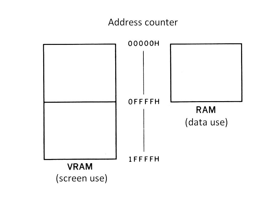
1.2 VRAM
MSX-VIDEO can be connected with 128K bytes VRAM (Video RAM) and 64K bytes expanded RAM. MSX-VIDEO has a 17-bit counter for accessing this 128K bytes address area. Note that this memory is controlled by MSX-VIDEO and cannot be directly accessed by the CPU.
Expanded RAM memory cannot be directly displayed to the screen as can that of VRAM. However, it can be manipulated the same as VRAM when using the video processor commands. This large work area is very useful when processing screen data. Note that the MSX standard does not include instructions regarding expanded RAM, so taking advantage of this in program design could result in compatibility problems with other MSX machines.
Figure 4.1 VRAM and expanded RAM
1.3 I/O ports
MSX-VIDEO has four I/O ports that send data back and forth the CPU. The functions of these ports are listed in Table 4.3. The ports are accessed by the CPU through its I/O addresses in the table below, addresses expressed as n, n’ are stored at address locations 6 and 7 in MAIN-ROM. Although n = n’ = 98H normally, this can be different on some machines, so port addresses should be obtained from these addresses for reliable results.
It is generally recommended that BIOS be used for I/O operations for purposes of compatibility. However, the screen display often requires high speed, so these I/O ports are capable of accessing MSX-VIDEO directly.
Table 4.3 MSX-VIDEO ports
----------------------------------------------------------------------
|      Port       | Address |               Function                 |
|-----------------+---------+----------------------------------------|
| port #0 (READ)  |    n    | read data from VRAM                    |
| port #0 (WRITE) |    n'   | write data to VRAM                     |
| port #1 (READ)  |  n + 1  | read status register                   |
| port #1 (WRITE) |  n'+ 1  | write to control register              |
| port #2 (WRITE) |  n'+ 2  | write to palette register              |
| port #3 (WRITE) |  n'+ 3  | write to indirectly specified register |
----------------------------------------------------------------------
Note: The value of n should be obtained by referring to address 6 in MAIN-ROM The value of n’should be obtained by referring to address 7 in MAIN-ROM
2. ACCESS TO MSX-VIDEO
MSX-VIDEO can be accessed directly through the I/O ports without going through BIOS. This section describes how to do this.
2.1 Access to Registers
2.1.1 Writing data to control registers
The control registers are write-only registers. As described above, the partial contents of control registers (R#0 to R#23) can be obtained by referring to VDP(n) from BASIC. This only reads the value which has been written in the work area of RAM (F3DFH to F3E6H, FFE7H to FFF6H) used for writing to registers.
There are three ways, described below, to write data to control registers. Since MSX accesses MSX-VIDEO inside the timer interrupt routine to examine the occurrence of sprite conflicts, note that access procedure will not inhibiting the interrupt when the registers are accessed in the proper way as described below.
(1) Direct access
The first way is to directly specify the data and where it is to be written to. Figure 4.2 illustrates the procedure. The data is first written to port#1 and then the destination register number is written to port#1 using the five least significant bits. The most significant bit is set to 1 and the second bit is set to 0. Thus the value would be 10XXXXXB in binary notation where XXXXX is the destination register number.
Figure 4.2 Direct access to R#n
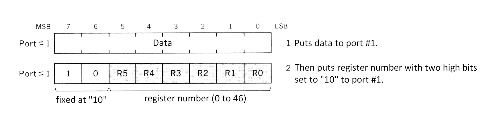
Port#1 is also used to set VRAM addresses and is described in section 2.2. The most significant bit of the second byte sent to this port is the address/register flag and determines the operation to take place. When the bit is set to “1”, writing data to a control register as described here will take place.
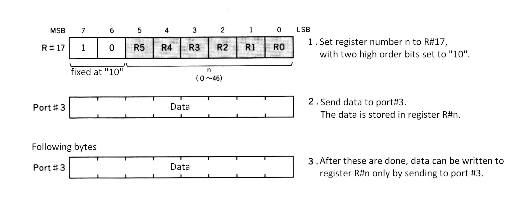
(2) Indirect Access (non-autoincrement mode)
The second way is to write data to the register specified as the objective register (R#17 contains the objective pointer). To begin with, store the register number to be accessed in R#17 by direct access. The most significant bit is set to 1 and the second bit to 0. Thus the value would be 10XXXXXB in binary notation where XXXXX is the objective register number. After this is done, data can be written to the objective register by sending data to port#3. This method is used for sending data to the same register continuously. An example would be for the execution of VDP commands.
Figure 4.3 Indirect access to R#n (non-autoincrement mode)
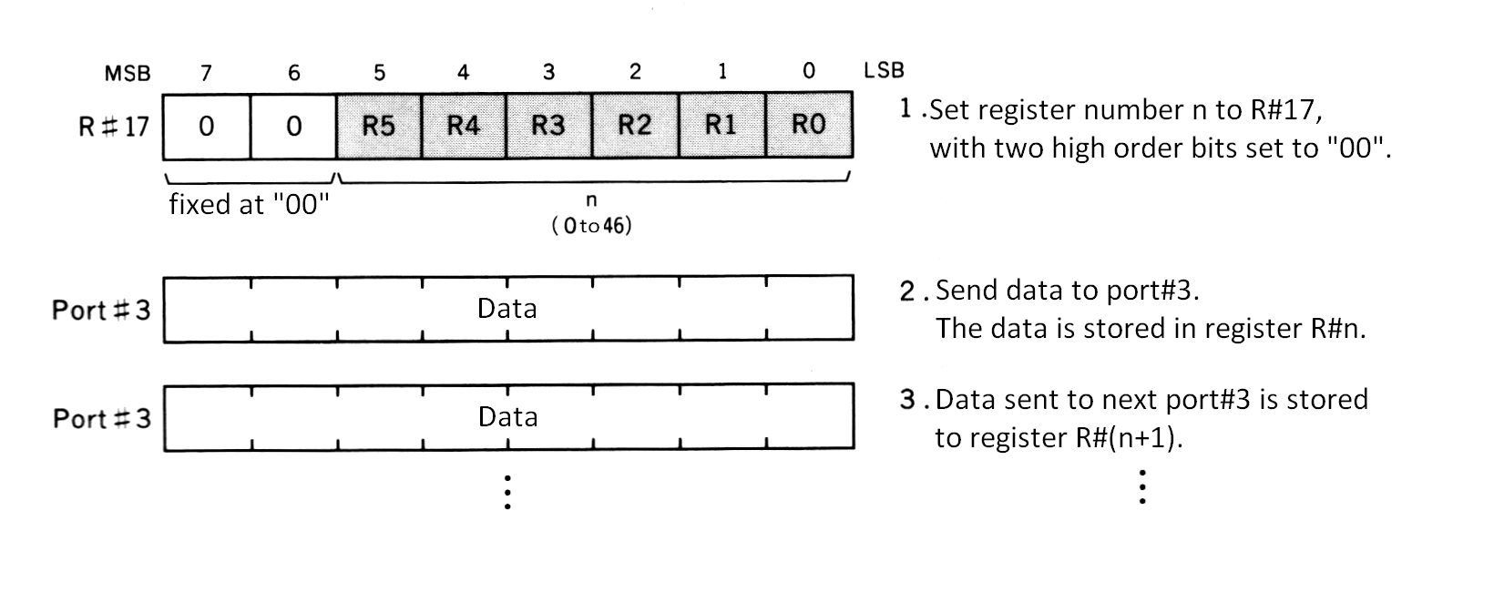
(3) Indirect Access (autoincrement mode)
The third way is to write date to the register indicated by R#17. R#17 is incremented each time data is sent to port#3. To begin with, store the beginning register number to be accessed in R#17 by direct access. The two most significant bits are set to 0. Thus the value would be 00XXXXXB in binary notation where XXXXX is the beginning register number.
Since this method allows writing data to continuous control registers effectively, it is useful when several continuous registers are to be changed at once. One example would be when the screen mode is changed.
Figure 4.4 Indirect access to R#n (autoincrement mode)
2.1.2 Setting a palette
To set data in the MSX-VIDEO palette registers (P#0 to P#15), specify the palette register number in the four lowest significant bits of R#16 (color palette pointer), and then send the data to port#2. Since palette registers have a length of 9 bits, data must be sent twice; red brightness and blue brightness first, then green brightness. Brightness is specified in the lower three bits of a four bit segment. Refer to Figure 4.5 for details.
After data is sent to port#2 twice, R#16 is automatically incremented. This feature makes it easy to initialize all the palettes.
Figure 4.5 Setting a colour palette register
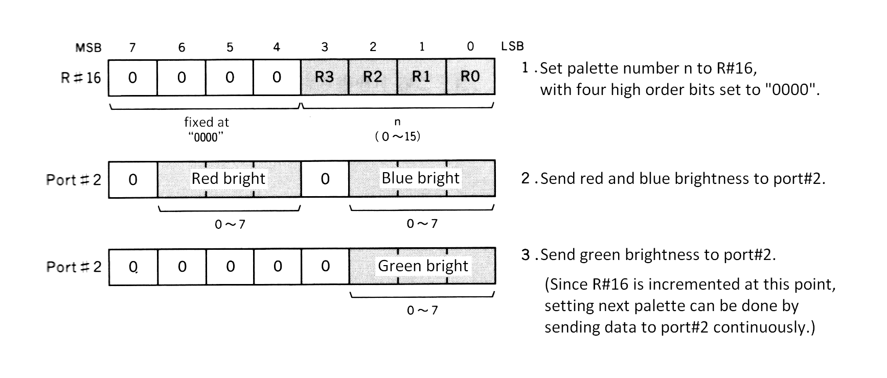
(*) Since R#16 is incremented at this point, setting next palette can be done by sending data to port#2 continuously.
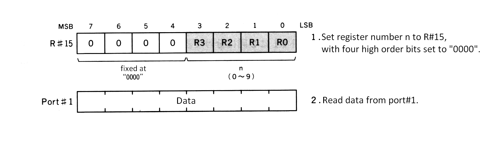
2.1.3 Reading status registers
Status registers are read-only registers. Their contents can be read from port#1 by setting the status register number in the least significant four bits of R#15 (status register pointer) as shown in Figure 4.6. The four most significant bits are set to 0. Thus the value would be 0000XXXXB in binary notation where XXXX is the status register number. Interrupts should be inhibited before the status register is accessed. After the desired task is completed, R#15 should be set to 0 and the interrupts released.
Figure 4.6 Acessing status registers
2.2 VRAM Access From the CPU
When a VRAM address is to be accessed from the CPU, follow the procedure described below.
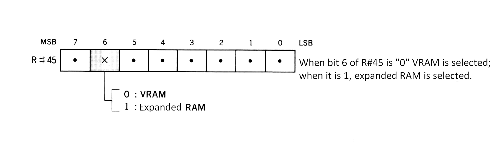
(1) Bank switching
The first 64K bytes of VRAM (00000H to 0FFFFH) and the 64K bytes of expanded RAM both reside at the same address space as viewed by MSX-VIDEO. Bank switching is used so that they can both be online at the same time. Since MSX2 does not to use expanded VRAM, always select the VRAM bank. Bank switching is controlled by bit 6 of R#45.
Figure 4.7 VRAM/expanded RAM bank switching
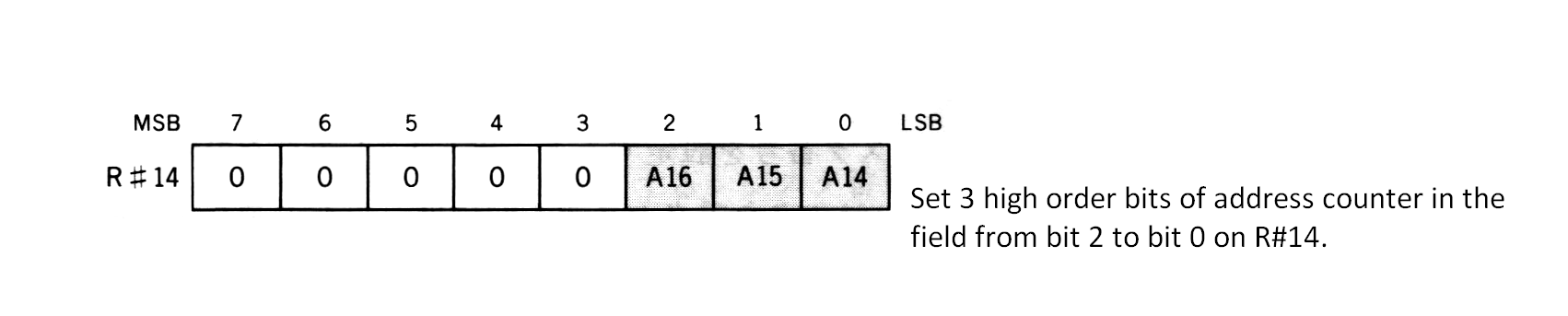
(2) Setting the VRAM page (three high order bits)
The 17-bit address for accessing the 128K bytes of VRAM is set in the address counter (A16 to A0). R#14 contains the three high order bits (A16 to A14). So this register can be viewed as switching between eight 16K byte pages of VRAM.
Figure 4.8 Setting the VRAM page (3 high order bits)
(3) Setting the VRAM address (14 low order bits)
The 14 low order bits of the address should be sent to port#1 in two bytes. Figure 4.9 shows the details. Make sure that the most significant bit of the second byte sent is set to 0. This sets the address/register flag to address mode. The second most significant bit sets the read/write flag. 1 signifies writing to VRAM and 2 signifies reading from VRAM.
Figure 4.9 Setting 14 low order bits
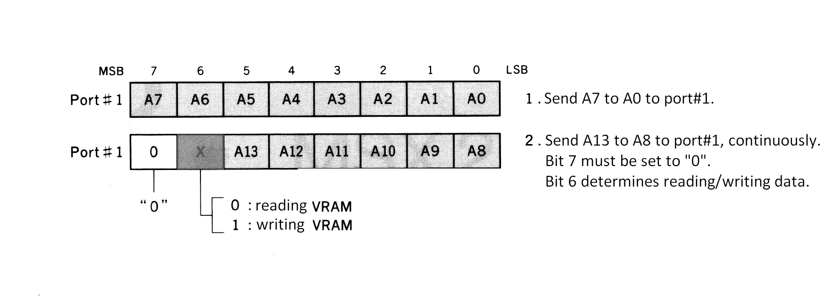
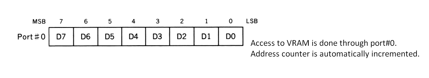
(4) Reading/writing VRAM
After setting the value in the address counter, read or write data through port#0. The read/write flag is set the same time as A13 to A8 of the address counter, as described above.
The address counter is automatically incremented each time a byte of data is read or written to port #0. This feature allows for easy access of continuous memory in VRAM.
Figure 4.10 Access to VRAM through port#0
3. SCREEN MODES OF THE MSX2
The MSX2 has ten different modes as shown in Table 4.4. Six screen modes marked with “*“ in the table below (TEXT 2 and GRAPHIC 3 to GRAPHIC 7) have been introduced for the MSX2. The other modes have been improved due to the change from TMS9918A to MSX-VIDEO. Fetures of these ten screen modes and how to use them are described below.
Table 4.4 Screen modes listing of MSX2
--------------------------------------------------------------------------
|  Mode Name  | SCREEN mode |                 Description                |
|-------------+-------------+--------------------------------------------|
|   TEXT 1    |  SCREEN 0   | 40 characters per line of text, one colour |
|             |  (width=40) | for each character                         |
|-------------+-------------+--------------------------------------------|
| * TEXT 2    |  SCREEN 0   | 80 characters per line of text,            |
|             |  (width=80) | character blinkable selection              |
|-------------+-------------+--------------------------------------------|
| MULTI-COLOR |  SCREEN 3   | pseudo-graphic, one character              |
|             |             | divided into four block                    |
|-------------+-------------+--------------------------------------------|
|   GRAPHIC 1 |  SCREEN 1   | 32 characters per one line of              |
|             |             | text, the COLOURed character available     |
|-------------+-------------+--------------------------------------------|
|   GRAPHIC 2 |  SCREEN 2   | 256 x 192, the colour is                   |
|             |             | specififed for each 8 dots                 |
|-------------+-------------+--------------------------------------------|
| * GRAPHIC 3 |  SCREEN 4   | GRAPHIC 2 which can use sprite             |
|             |             | mode 2                                     |
|-------------+-------------+--------------------------------------------|
| * GRAPHIC 4 |  SCREEN 5   | 256 x 212; 16 colours are                  |
|             |             | available for each dot                     |
|-------------+-------------+--------------------------------------------|
| * GRAPHIC 5 |  SCREEN 6   | 512 x 212; 4 colours are                   |
|             |             | available for each dot                     |
|-------------+-------------+--------------------------------------------|
| * GRAPHIC 6 |  SCREEN 7   | 512 x 212; 16 colours are                  |
|             |             | available for each dot                     |
|-------------+-------------+--------------------------------------------|
| * GRAPHIC 7 |  SCREEN 8   | 256 x 212; 256 colours are                 |
|             |             | available for each dot                     |
--------------------------------------------------------------------------
3.1 TEXT 1 Mode
TEXT 1 screen mode has the following features:
----------------------------------------------------------------------------
| screen:               40 (horizontal) x 24 (vertical)                    |
|                       background/character colours can be selected from  |
|                       512 colours                                        |
| character:            256 characters available                           |
|                       character size: 6 (horizontal) x 8 (vertical)      |
| memory requirements:  for character font ... 2048 bytes                  |
|                                              (8 bytes x 256 characters)  |
|                       for display ........... 960 bytes                  |
|                                               (40 characters x 24 lines) |
| BASIC:                compatible with SCREEN 0 (WIDTH 40)                |
----------------------------------------------------------------------------
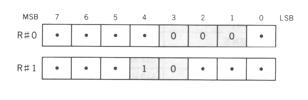
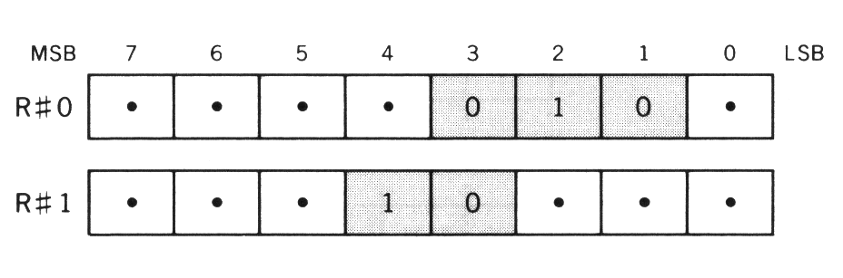
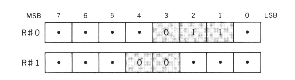
3.1.1 Setting TEXT 1 mode
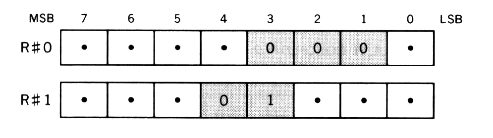
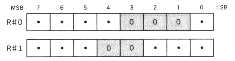
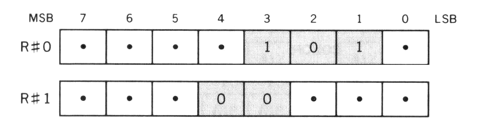
MSX-VIDEO screen modes are set by using 5 bits of R#0 and R#1. Figure 4.11 shows the details. The 3-bit mask in R#0 is 000B and the 2-bit mask in R#1 is 10B when using the TEXT 1 mode.
Figure 4.11 Setting TEXT1 mode
3.1.2 Screen structure of TEXT 1 mode
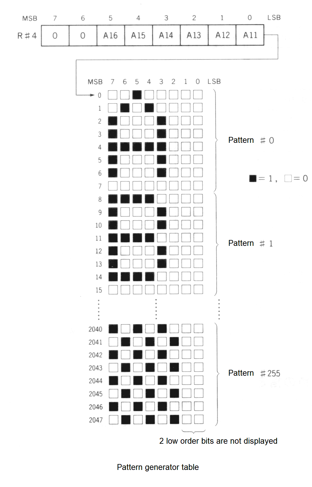
Pattern generator table
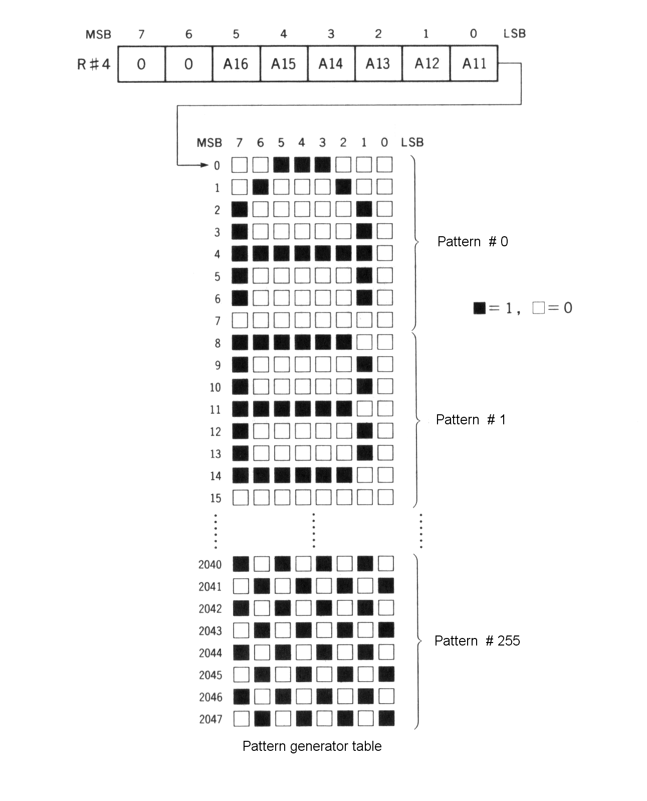
The area in which character fonts are stored is called the pattern generator table. This table is located in VRAM, and, although the font is defined by using 8 bytes for each character from the top of the table, the 2 low order bits of each byte representing the right two columns are not displayed on the screen. Thus, the size of one character is 6 x 8 pixels. Each character font set contains 256 different characters numbered from 0 to 255. Use this code to specify which character should be displayed on the screen.
Specify the location of the pattern generator table in R#4. Note that the 6 high order bits of the address (A16 to A11) are specified and the 11 low order bits of the address (A10 to A0) are always 0 (“00000000000B”). So the address in which the pattern generator table can be set always begins at a multiple of 2K bytes from 00000H. This address can be found using the system variable BASE(2) from BASIC. Figure 4.12 shows the structure of the pattern generator table.
Figure 4.12 Structure of the pattern generator table
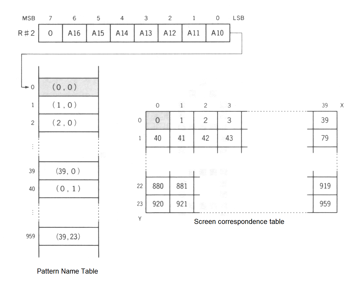
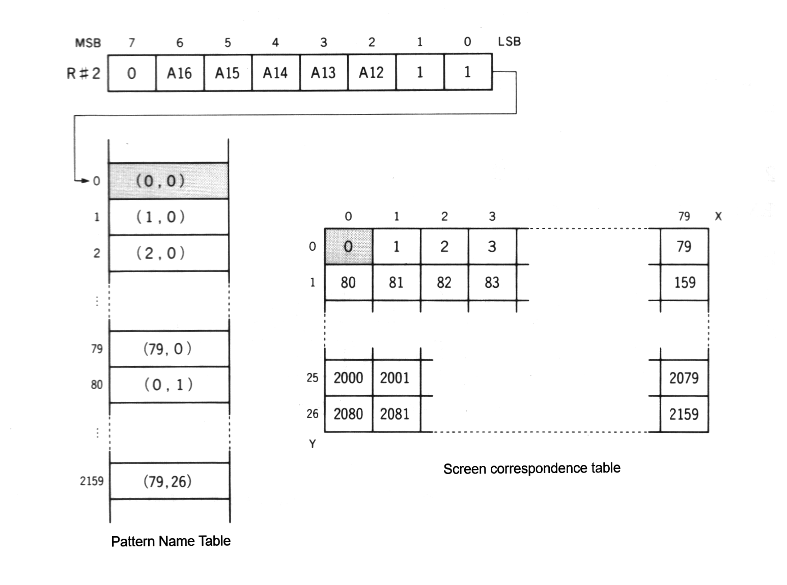
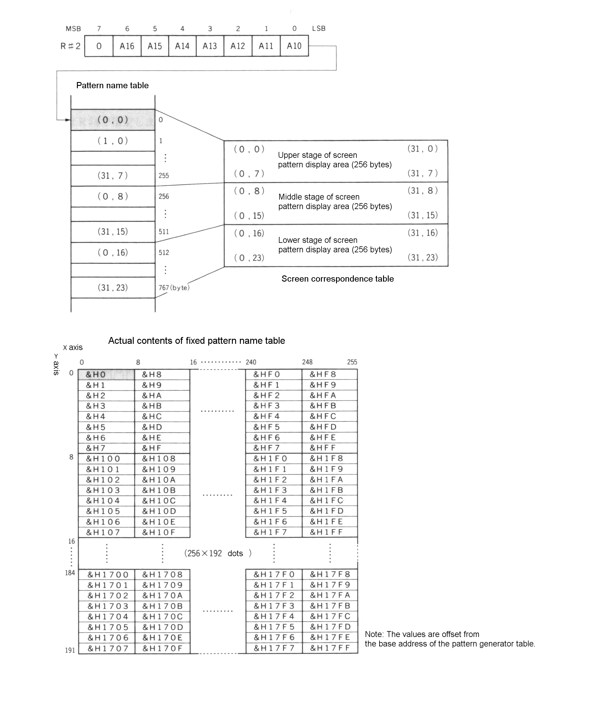
Pattern name table
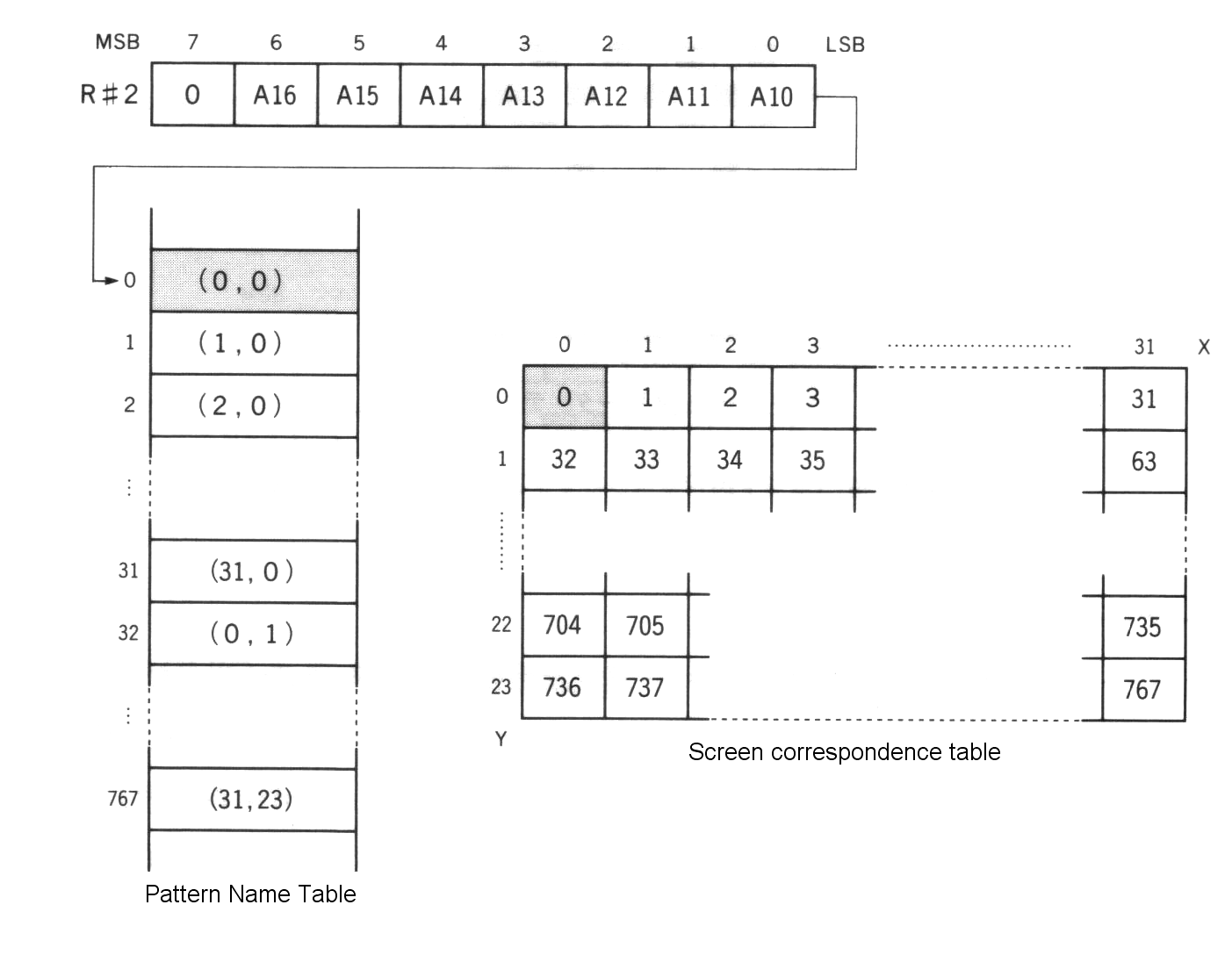
The pattern name table stores the characters to be displayed at each position on the screen. One byte of memory is used for each character to be displayed. Figure 4.13 shows the correspondence between memory location and screen location.
Specify the location of the pattern generator table in R#2. Note that the 7 high order bits of the address (A16 to A10) are specified and that the 10 low order bits of the address (A9 to A0) are always 0 (“0000000000B”). So the address in which the name table can be set always begins at a multiple of 1K bytes from 00000H. This address can be found by using the system variable BASE(0) from BASIC. Figure 4.13 shows the structure of the pattern generator table.
Figure 4.13 Structure of TEXT1 pattern name table
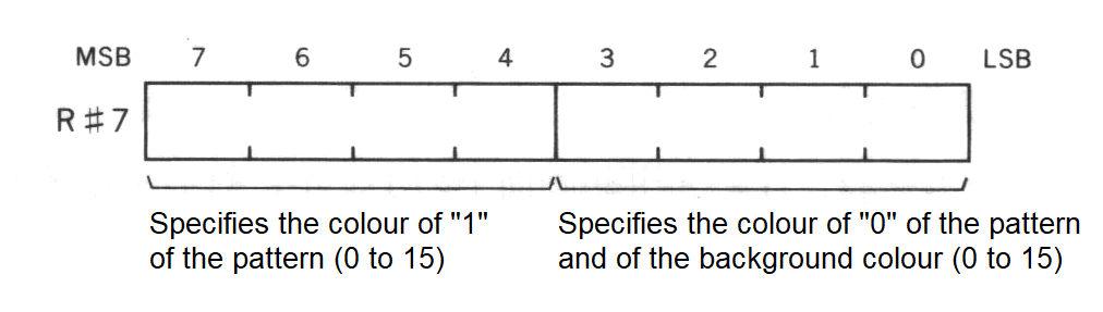
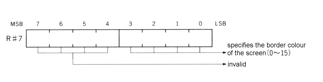
3.1.3 Specifying screen colour
The screen colour is specified by R#7. The background colour is the palette specified by the 4 low-order bits of R#7; the 4 high-order bits specify the foreground colour (see Figure 4.14). A “0” in the font pattern is displayed in the background colour and a “1” is displayed in the foreground colour. Note that in TEXT 1 the border colour of the screen cannot be set and it is the same as the background colour.
Figure 4.14 Colour specification in TEXT 1
3.2 TEXT 2 Mode
The screen mode TEXT 2 has the following features:
----------------------------------------------------------------------------
| screen:               80 (horizontal) x 24 (vertical) or 26.5 (vertical) |
|                       background colour/character colour can be selected |
|                       from 512 colours                                   |
| character:            256 characters available                           |
|                       character size: 6 (horizontal) x 8 (vertical)      |
|                       each character blinkable                           |
| memory requirements:  24 lines                                           |
|                          for character font ... 2048 bytes               |
|                                               (8 bytes x 256 characters) |
|                          for display .......... 1920 bytes               |
|                                               (80 characters x 24 lines) |
|                          for blinking .........  240 bytes (= 1920 bits) |
|                       26.5 lines                                         |
|                          for character font ... 2048 bytes               |
|                                               (8 bytes x 256 characters) |
|                          for display .......... 2160 bytes               |
|                                               (80 characters x 27 lines) |
|                          for blinking .........  270 bytes (= 2160 bits) |
| BASIC:                compatible with SCREEN 0 (WIDTH 80)                |
----------------------------------------------------------------------------
3.2.1 Setting TEXT 2 mode
Set TEXT2 mode as shown in Figure 4.15.
Figure 4.15 Setting TEXT2 mode
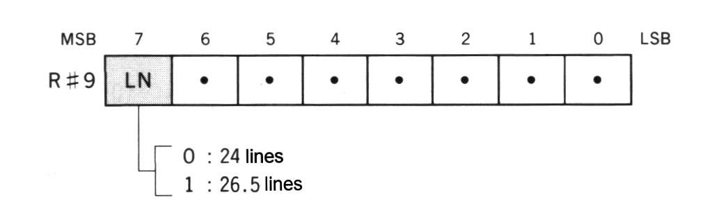
Setting number of lines (24 lines/26.5 lines)
TEXT2 mode can switch the screen to 24 lines or 26.5 lines depending on the value of bit 7 in R#9. Note that, when the screen is set to 26.5 lines, only the upper half of the characters at the bottom of the screen are displayed. This mode is not supported by BASIC.
Figure 4.16 Switching number of lines
3.2.2 Screen structure of TEXT 2
Pattern generator table
The pattern generator table has the same structure and function as the one of TEXT1. See the descriptions for TEXT1.
Pattern name table
Since the number of characters to be displayed in the screen has been increased to 2160 (80 x 27) characters maximum, the maximum area occupied by the pattern name table is 2160 bytes.
Specify the location of the pattern name table in R#2. The 5 high order bits of the address (A16 to A12) are specified and the 12 low order bits of the address (A11 to A0) are always 0 (“000000000000B”). So the address in which the pattern name table can be set always begins at a multiple of 4K bytes from 00000H.
Figure 4.17 Structure of TEXT2 pattern name table
Blink table
In TEXT2 mode, it is possible to set the blink attribute for each character. The blink table stores the information of the screen location of the characters blinked. One bit of the blink table corresponds to one character on the screen (that is, on the pattern name table). When the bit is set to “1” blinking is enabled for the corresponding character; when the bit is “0” blinking is disabled.
Figure 4.18 Blink table structure of TEXT2
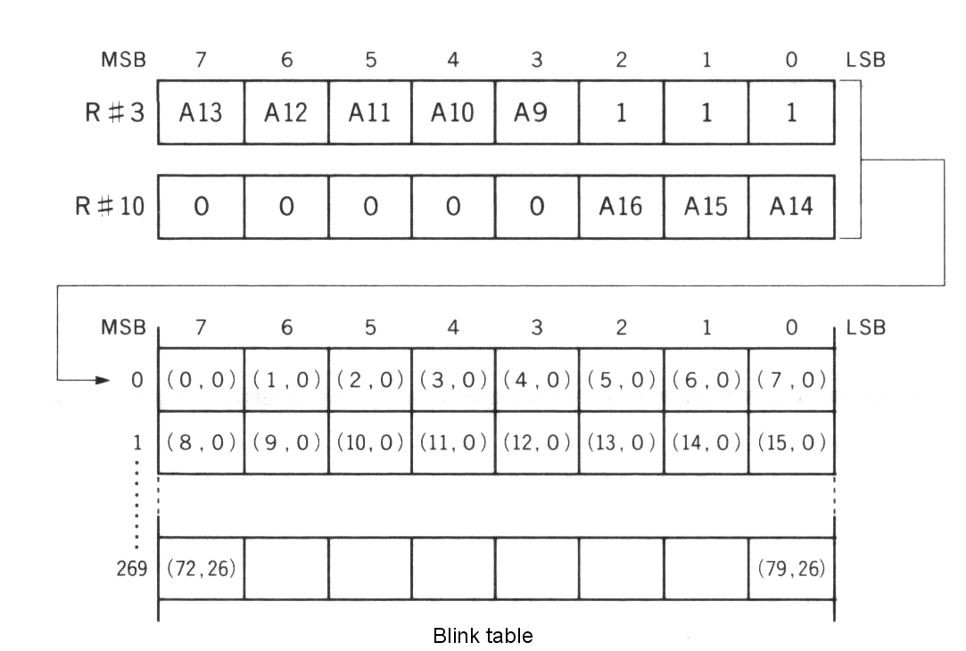
Specify the starting address of the blink table by setting the 8 high order bits (A16 to A9) in R#3 and R#10. The location of the blink table is set by writing the 8 high order bits of the address (A16 to A9) in R#3 and R#10. The 9 low order bits of the address (A8 to A0) are always 0 (“000000000B”). So the address in which the blink table can be set always begins at a multiple of 512 bytes from 00000H.
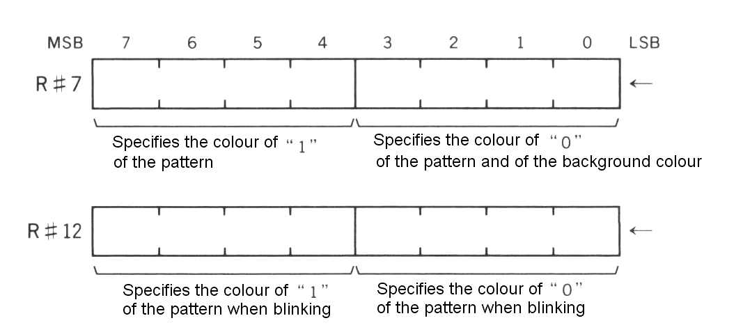
3.2.3 Screen colour and character blink specification
The foreground colour is specified by the 4 high order bits of R#7 and the background colour by the 4 low order bits of R#7. Characters with a blink attribute of 1 defined by the blink table alternate between the blink colour and the colour specified in R#12.
Figure 4.19 Setting screen colour and blink colour
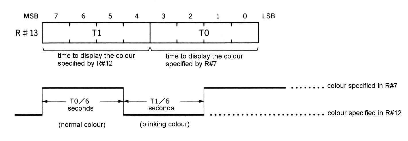
The blinking rate is set in R#13. The 4 high order bits define the display time in the original colour, and the 4 low order bits define the display time in the blink colour. The period of time is defined in units of 1/6 seconds.
Figure 4.20 Setting blink rate
List 4.1 Blink example
1000 '*********************************************************
1010 '  LIST 4.1  BLINK SAMPLE
1020 '*********************************************************
1030 '
1040 SCREEN 0 : WIDTH 80                'TEXT 2 mode
1050 ADR=BASE(1)                        'TAKE COLOR TABLE ADDRESS
1060 '
1070 FOR I=0 TO 2048/8
1080   VPOKE ADR+I,0                    'reset blink mode
1090 NEXT
1100 '
1110 VDP(7) =&HF1                       'text color=15, back color=1
1120 VDP(13)=&H1F                       'text color=1,  back color=15
1130 VDP(14)=&H22                       'set interval and start blink
1140 '
1150 PRINT "Input any character : ";
1160 '
1170 K$=INPUT$(1)
1180 IF K$<CHR$(28) THEN 1230
1190 IF K$>" " THEN GOSUB 1280
1200 PRINT K$;
1210 GOTO 1170
1220 '
1230 VDP(14)=0                          'stop blink
1240 END
1250 '
1260 '----- set blink mode -----
1270 '
1280 X=POS(0) : Y=CSRLIN
1290 A=(Y*80+X)\8
1300 B=X MOD 8
1310 M=VAL("&B"+MID$("000000010000000",8-B,8))
1320 VPOKE ADR+A,VPEEK(ADR+A) XOR M
1330 RETURN
3.3 MULTI COLOUR Mode
The MULTI COLOUR mode is described below:
----------------------------------------------------------------------------
| screen:               64 (horizontal) x 48 (vertical) blocks             |
|                       16 colours from 512 colours can be displayed       |
|                       at the same time                                   |
| block:                block size is 4 (horizontal) x 4 (vertical) dots   |
|                       colour can be specified to each block              |
| memory requirements:  for setting colours ........... 2048 bytes         |
|                       for specifying locations ......  768 bytes         |
| sprite:               sprite mode 1                                      |
| BASIC:                compatible to SCREEN 3                             |
----------------------------------------------------------------------------
3.3.1 Setting MULTI COLOUR mode
Set MULTI COLOUR mode as shown in Figure 4.21.
Figure 4.21 Setting MULTI COLOUR mode
Pattern generator table
In this mode, patterns are constructed as 2 x 2 blocks and one pattern name corresponds to four patterns. The starting address on this table is specified in R#4. Since only the 6 high order bits (A16 to A11) of the address is specified, the pattern generator table can be located at intervals of 2K bytes from 00000H (see Figure 4.22).
Figure 4.22 Pattern generator table structure of MULTI COLOUR
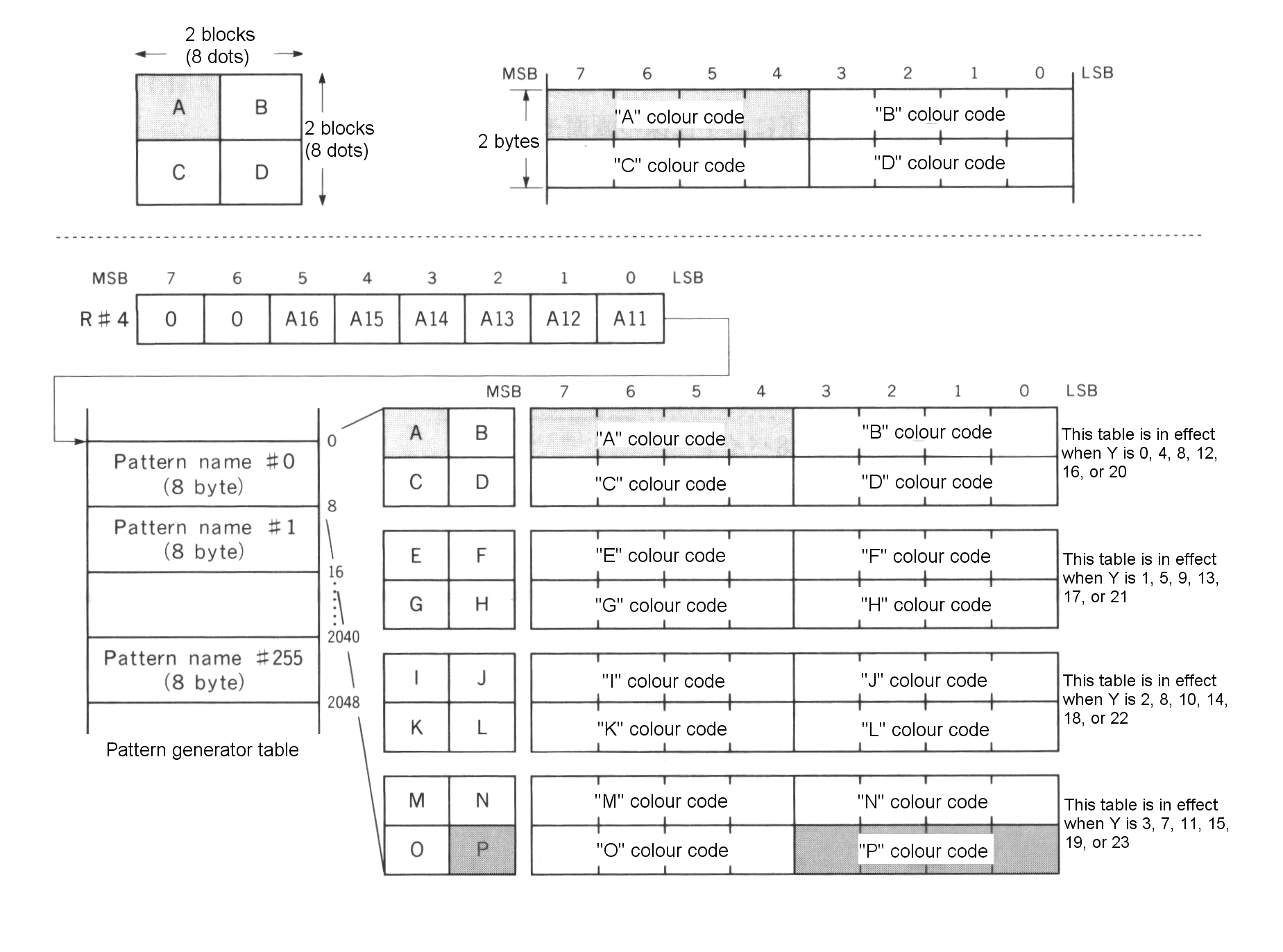
(1) This table is in effect when Y is 0, 4, 8, 12, 16, or 20 (2) This table is in effect when Y is 1, 5, 9, 13, 17, or 21 (3) This table is in effect when Y is 2, 8, 10, 14, 18, or 22 (4) This table is in effect when Y is 3, 7, 11, 15, 19, or 23
Pattern name table
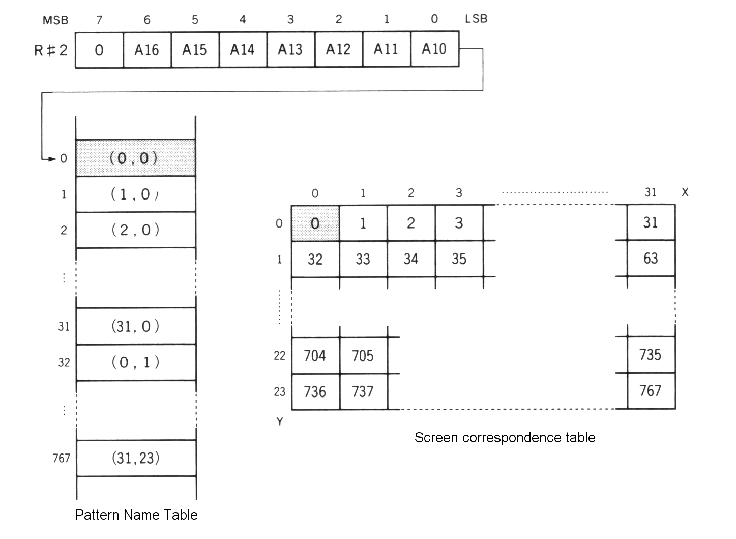
This is the table for displaying specified patterns at desired locations on the screen. One of four patterns in a pattern name is displayed at its Y-coordinate value. BASIC sets the contents of this table as shown in Figure 4.23. The starting address of the pattern name table is specified by R#2. Since only the 7 high order bits of the address (A16 to A10) are specified, the address at which this table can be set is at increments of 1K bytes from 00000H (see Figure 4.24).
Figure 4.23 Setting BASIC pattern name table
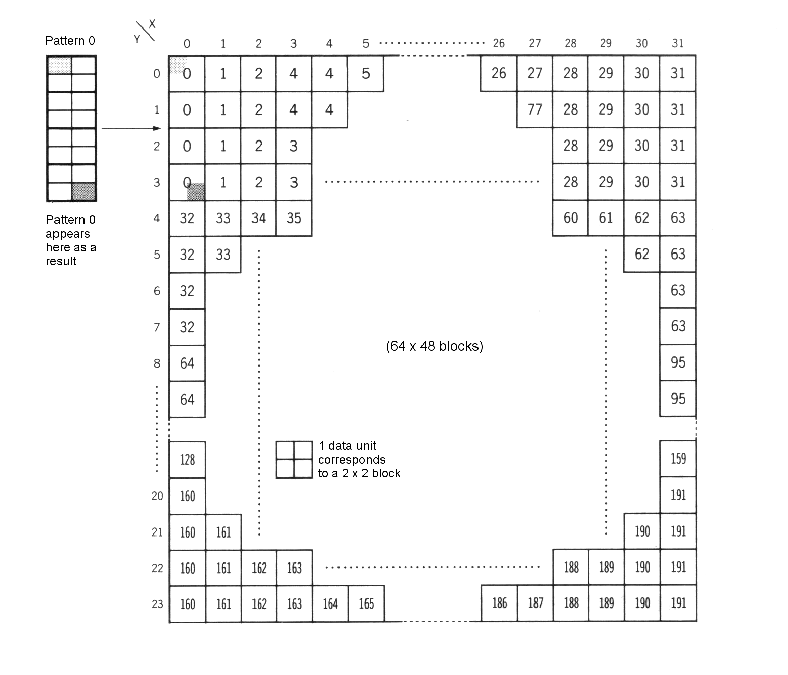
Figure 4.24 Pattern name table structure of MULTI COLOUR mode
3.3.3 Specifying the screen colour in MULTI COLOUR mode
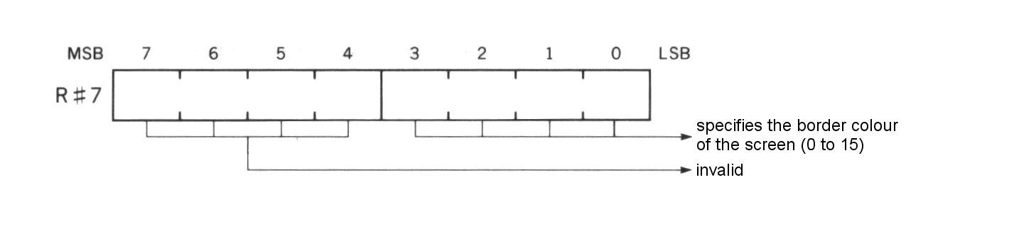
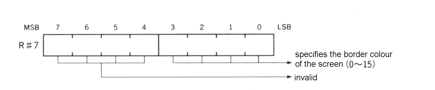
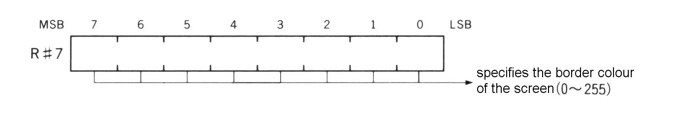
The border colour of the screen can be specified by R#7 (see Figure 4.25).
Figure 4.25 Border colour specification
3.4 GRAPHIC 1 Mode
GRAPHIC 1 Mode is the screen mode as shown below:
----------------------------------------------------------------------------
| screen:               32 (horizontal) x 24 (vertical) patterns           |
|                       16 from 512 colours can be displayed               |
|                       at the same time                                   |
| pattern:              256 kinds of patterns are available                |
|                       pattern size is 8 (horizontal) x 8 (vertical) dots |
|                       any Figure can be defined for each pattern         |
|                       different colour for each 8 pattern can be set     |
| memory requirements:  for pattern font .............. 2048 bytes         |
|                       for colour table ..............   32 bytes         |
| sprite:               sprite mode 1                                      |
| BASIC:                compatible with SCREEN 1                           |
----------------------------------------------------------------------------
3.4.1 Setting GRAPHIC 1 mode
GRAPHIC 1 mode can be set as shown in Figure 4.26.
Figure 4.26 Setting GRAPHIC 1 mode
3.4.2 Screen structure of GRAPHIC 1 mode
Pattern generator table
In this mode, 256 kinds of patterns, corresponding to codes 0 to 255, can be displayed on the screen. Fonts of each pattern are defined in the pattern generator table (see Figure 4.27). The starting address of the pattern generator table is specified by R#4. Note that only the 6 high order bits of the address (A16 to A11) are specified.
Figure 4.27 Pattern generator table of GRAPHIC 1 mode
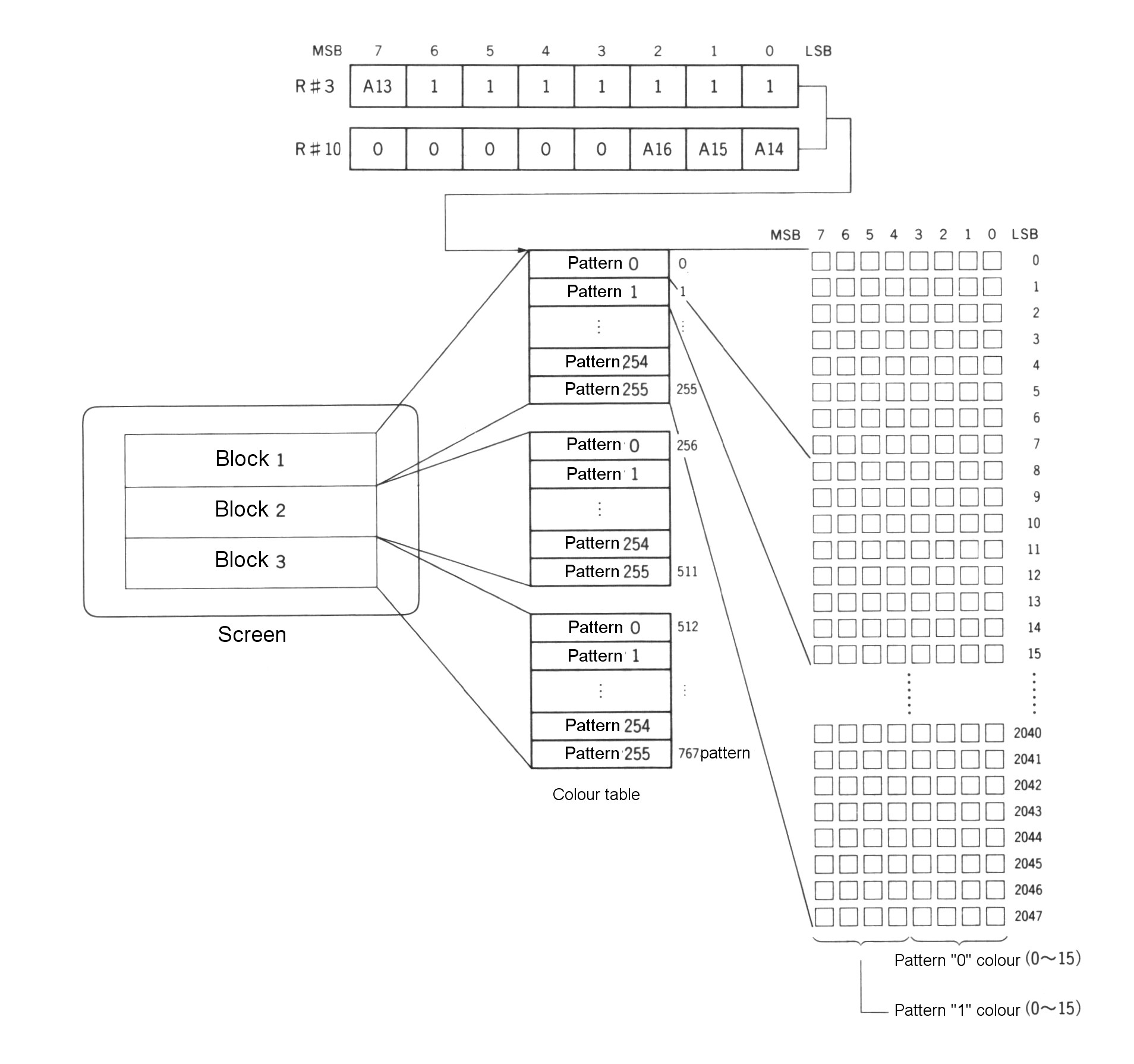
Colour table
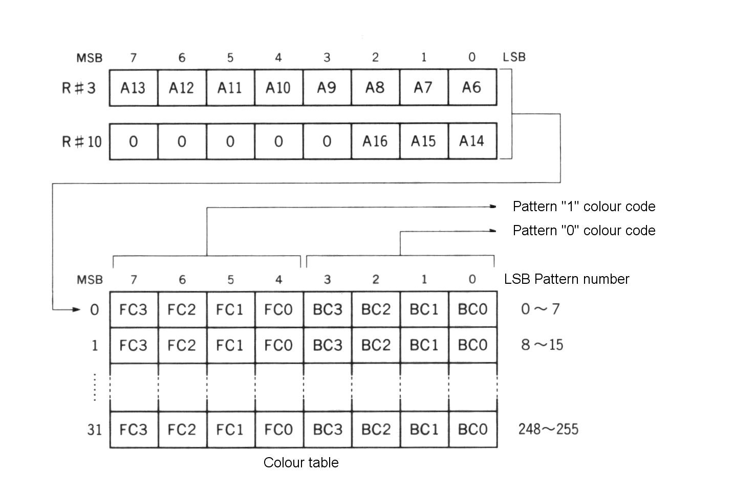
The colour specification for each of the 8 patterns are done by the colour table. Colours for “0” and “1” of the bit of each pattern can be specified (see Figure 4.28). The starting address of the colour table is specified by R#3 and R#10. Note that only the 11 high order bits of the address (A16 to A6) are specified.
Figure 4.28 Colour table structure of GRAPHIC 1 mode
Pattern name table
The size of the pattern name table is 768 bytes and the table corresponds to the pattern on the screen, one by one (see Figure 4.29). The starting address of the pattern name table is specified by R#2. Note that only the 7 high order bits of the address (A16 to A10) are specified.
Figure 4.29 Pattern name table structure of GRAPHIC 1 mode
3.4.3 Specifying the screen colour
The border colour of the screen can be specified by R#7 (see Figure 4.30).
Figure 4.30 Screen colour specification of GRAPHIC 1 mode
3.5 GRAPHIC 2, GRAPHIC 3 modes
GRAPHIC 2 and GRAPHIC 3 modes are the screen modes as described below:
----------------------------------------------------------------------------
| screen:               32 (horizontal) x 24 (vertical) patterns           |
|                       16 from 512 colours can be displayed               |
|                       at the same time                                   |
| pattern:              768 kinds of patterns are available                |
|                       pattern size is 8 (horizontal) x 8 (vertical) dots |
|                       any Figure can be defined for each pattern         |
|                       only two colours can be used in horizontal 8 dots  |
| memory requirements:  for pattern font .............. 6144 bytes         |
|                       for colour table .............. 6144 bytes         |
| sprite:               sprite mode 1 for GRAPHIC 2                        |
|                       sprite mode 2 for GRAPHIC 3                        |
| BASIC:                compatible to SCREEN 2 for GRAPHIC 2               |
|                       compatible to SCREEN 4 for GRAPHIC 3               |
----------------------------------------------------------------------------
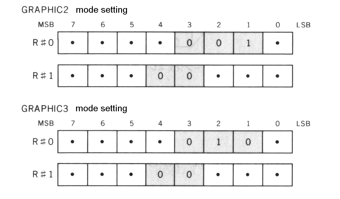
3.5.1 Setting GRAPHIC 2, GRAPHIC 3 modes
GRAPHIC 2, and GRAPHIC 3 modes are set as Figure 4.31.
Figure 4.31 Setting GRAPHIC 2, GRAPHIC 3 modes
3.5.2 Screen structure of GRAPHIC 2, GRAPHIC 3 modes
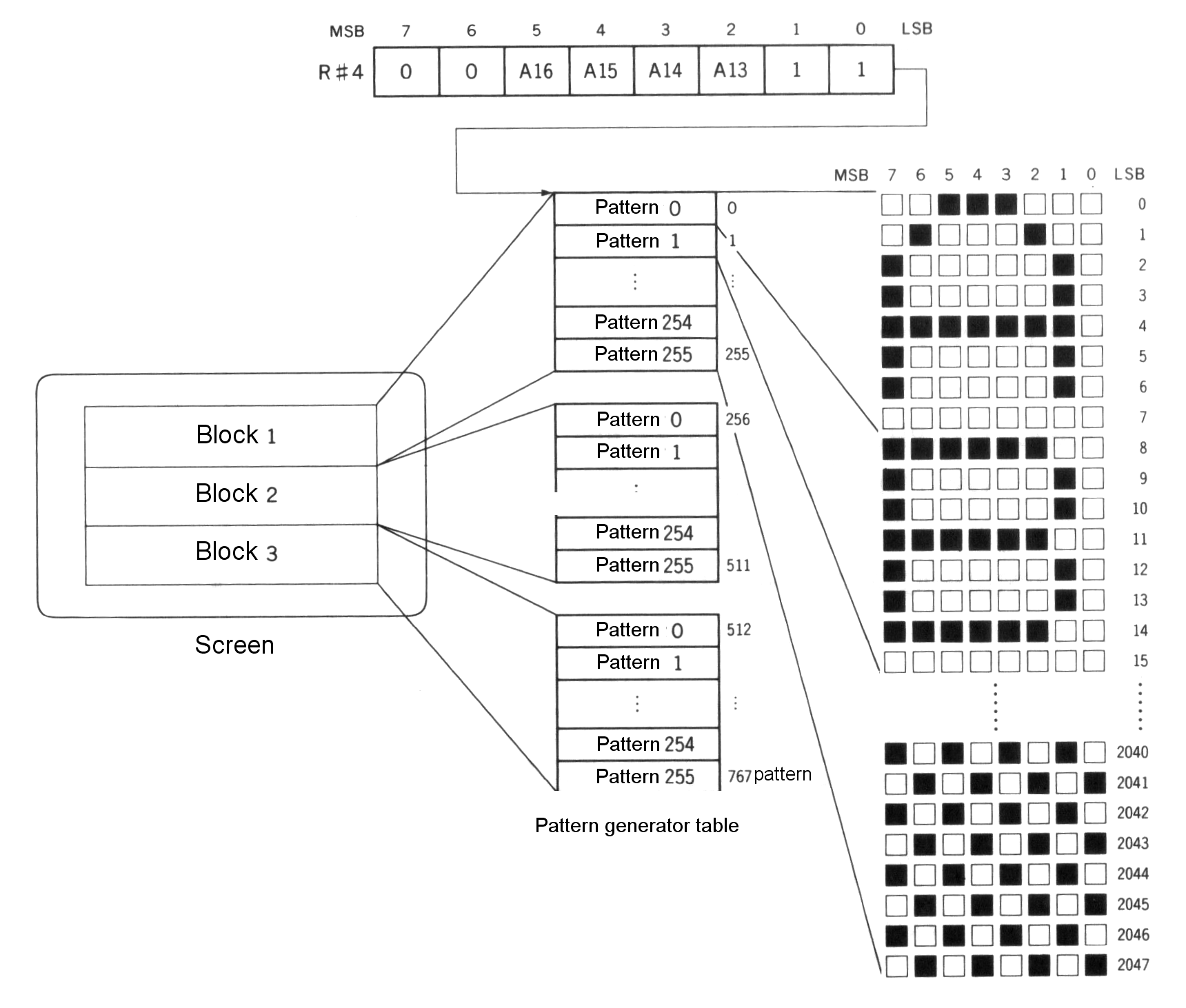
Pattern generator table
In this mode, there are three pattern generator tables which are compatible with GRAPHIC 1 and 768 patterns can be displayed. It cannot display patterns which are overlapped on the screen, and operating the pattern generator table in this case causes the 256 x 192 dot graphics display to be simulated. The starting address of the pattern generator table is specified by R#4. Note that only 4 bits of the address (A16 to A13) are specdified, so the address which can be set is located at interval steps of 8K bytes from 00000H (see Figure 4.32).
Figure 4.32 Pattern generator table structure of GRAPHIC 2, GRAPHIC 3
Colour table
The size of the colour table is the same as that of the pattern generator table and colours for “0” and “1” bits of each horizontal line of each pattern can be specified (see Figure 4.33). The starting address of the colour table is specified by R#3 and R#10. Note that only the 4 high order bits of the address (A16 to A13) is specified.
Figure 4.33 Colour table structure of GRAPHIC 2, GRAPHIC 3 modes
Pattern name table
The pattern name table is divided into three stages - upper, middle, and lower; each displays the pattern by referring to 256 bytes of the pattern generator (see Figure 4.34). This method enables each of 768 bytes on the pattern name table to display a different pattern font.
Figure 4.34 Pattern name table for GRAPHIC modes 2 and 3
3.5.3 Screen colour specification
The border colour of the screen can be specified by R#7 (see Figure 4.35).
Figure 4.35 Screen colour specification of GRAPHIC 2, GRAPHIC 3 modes
3.6 GRAPHIC 4 Mode
GRAPHIC 4 mode is described below:
----------------------------------------------------------------------------
| screen:               256 (horizontal) x 212 (vertical) dots             |
|                       (or, 192 vertical)                                 |
|                       16 colours can be displayed at the same time       |
|                       each of 16 colours can be selected from 512 colours|
| command:              high speed graphic by VDP command available        |
| sprite:               mode 2 sprite function available                   |
| memory requirements:  for 192 dots                                       |
|                         bitmap screen ....... 24K bytes (6000H bytes)    |
|                         (4 bits x 256 x 192)                             |
|                       for 212 dots                                       |
|                         bitmap screen ....... 26.5K bytes (6A00H bytes)  |
|                         (4 bits x 256 x 212)                             |
| BASIC:                compatible to SCREEN 5                             |
----------------------------------------------------------------------------
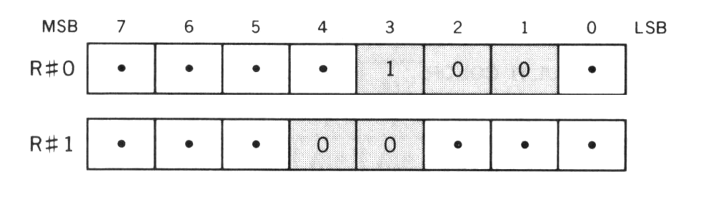
3.6.1 Setting GRAPHIC 4 mode
Set GRAPHIC 4 mode as shown in Figure 4.36.
Figure 4.36 GRAPHIC 4 mode setting
3.6.2 Screen structure of GRAPHIC 4 mode
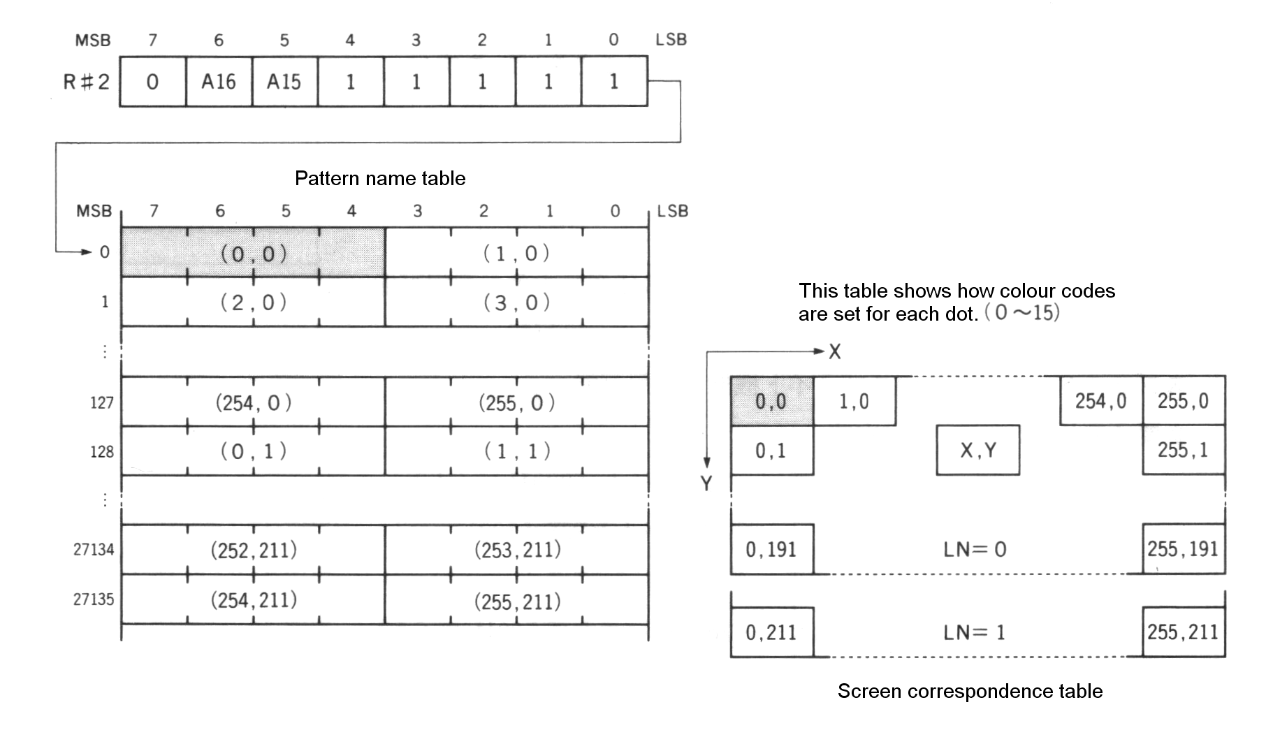
Pattern name table
In GRAPHIC 4 mode, one byte of the pattern name table corresponds with 2 dots on the screen. The colour information of each dot is represented by 4 bits and 16 colours can be specified (see Figure 4.37). The starting address of the pattern name table is specified by R#2. Only the 2 high order bits of the address (A16 to A15) are specified and the 15 low order bits are considered as “0”. Thus, the four addresses at which the pattern name can be set are 00000H, 08000H, 10000H, and 18000H.
Figure 4.37 Pattern name table structure of GRAPHIC 4 mode
The dot at (X,Y) coordinate on the screen can be accessed by using Expression 4.1. The program of List 4.2 illustrates the use of Expression 4.1.
Expression 4.1 The expression for accessing the dot at (X,Y) coordinate
ADR = X/2 + Y * 128 + base address
(The colour of the dot is represented by 4 high order bits in the case that X is even and by 4 low order bits in the case that X is odd.)
List 4.2 PSET for GRAPHIC 4 mode written in BASIC
100 '*********************************************
110 '  LIST 4.2   dot access of GRAPHIC 4 mode
120 '*********************************************
130 '
140 SCREEN 5
150 BA=0
160 FOR I=0 TO 255
170   X=I:Y=I\2
180   COL=15
190   GOSUB 1000
200 NEXT
210 END
220 '
1000 '****************************************
1010 '  PSET (X,Y),COL
1020 '   COL:color  BA:graphics Base Address
1030 '****************************************
1040 '
1050 ADR=X\2+Y*128+BA
1060 IF X AND 1 THEN BIT=&HF0:C=COL ELSE BIT=&HF:C=COL*16
1070 D=VPEEK(ADR)
1080 D=(D AND BIT) OR C
1090 VPOKE ADR,D
1100 RETURN
3.6.3 Screen colour specification
The border colour of the screen can be specified by R#7 (see Figure 4.38).
Figure 4.38 Screen colour specification in GRAPHIC 4 mode

3.7 GRAPHIC 5 Mode
GRAPHIC 5 mode is described as follows:
----------------------------------------------------------------------------
| screen:               512 (horizontal) x 212 (vertical) dots             |
|                       (or, 192 vertical)                                 |
|                       4 colours can be displayed at the same time        |
|                       each of 4 colours can be selected from 512 colours |
| command:              graphic command by hardware available              |
| sprite:               mode 2 sprite function available                   |
| memory requirements:  for 192 dots                                       |
|                         bitmap screen ....... 24K bytes (6000H bytes)    |
|                         (2 bits x 512 x 192)                             |
|                       for 212 dots                                       |
|                         bitmap screen ....... 26.5K bytes (6A00H bytes)  |
|                         (2 bits x 512 x 212)                             |
| BASIC:                compatible to SCREEN 6                             |
----------------------------------------------------------------------------
3.7.1 Setting GRAPHIC 5 mode
Set GRAPHIC 5 mode as shown in Figure 4.39.
Figure 4.39 GRAPHIC 5 mode setting
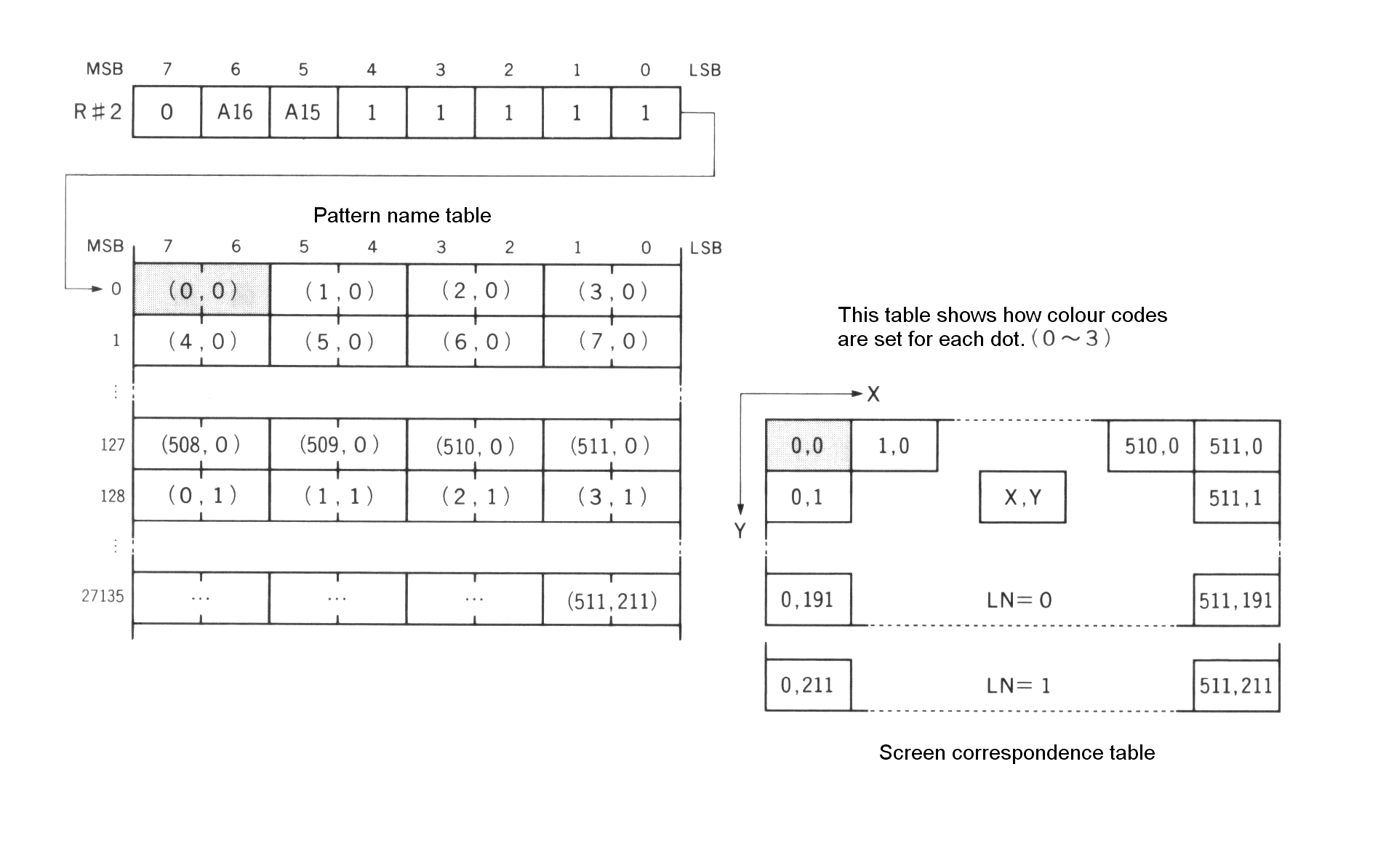
3.7.2 Pattern name table
In GRAPHIC 5 mode, one byte of the pattern name table corresponds with 4 dots on the screen. The colour information of each dot is represented by 2 bits and 4 colours can be specified. As with GRAPHIC 4 mode, the pattern name table is set by writing 2 high order bits of the address in R#2. The addresses can be set at either 00000H, 08000H, 10000H, or 18000H (see Figure 4.40).
Figure 4.40 Pattern name table structure of GRAPHIC 5 mode
The dot at (X,Y) coordinate on the screen can be accessed by using Expression 4.2. The program of List 4.3 confirms Expression 4.2.
Expression 4.2 The expression for accessing the dot at (X,Y) coordinate
ADR = X/4 + Y * 128 + base address
(The colour of the dot is represented by bit 7 and 6, or 5 and 4, or 3 and 2, or 1 and 0, when X MOD 4 is 0, or 1, or 2, or 3, respectively.)
List 4.3 PSET for GRAPHIC 5 mode written in BASIC
100 '*********************************************
110 '  LIST 4.3   dot access of GRAPHIC 5 mode
120 '*********************************************
130 '
140 SCREEN 6
150 BA=0
160 FOR I=0 TO 511
170   X=I : Y=I\2
180   COL=3
190   GOSUB 1000
200 NEXT
210 END
220 '
1000 '*******************************************
1010 '  PSET(X,Y)
1020 '   COL:colour  BA:graphic Base Address
1030 '*******************************************
1040 '
1050 ADR=X\4+Y*128+BA
1060 LP=X MOD 4
1070 IF LP=0 THEN BIT=&H3F:C=COL*&H40
1080 IF LP=1 THEN BIT=&HCF:C=COL*&H10
1090 IF LP=2 THEN BIT=&HF3:C=COL*&H4
1100 IF LP=3 THEN BIT=&HFC:C=COL
1110 D=VPEEK(ADR)
1120 D=(D AND BIT) OR C
1130 VPOKE ADR,D
1140 RETURN
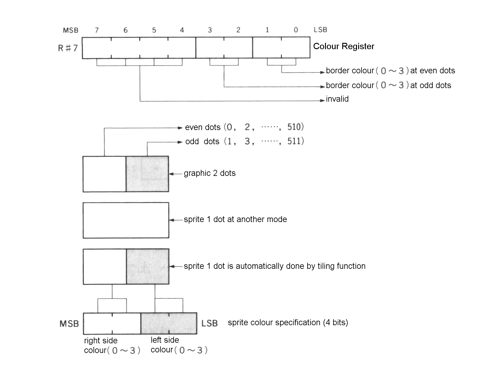
3.7.3 Setting the screen colour
In GRAPHIC 5 mode, hardware tiling is done for the border colour of the screen and sprites. As with the other modes, these colours are specified by 4 bits; 2 high order bits of 4 bits represents the dot colour at even locations, and 2 low order bits for the dot colour at odd locations (see Figure 4.41).
Figure 4.41 Screen colour specification in GRAPHIC 5 mode
3.8 GRAPHIC 6 Mode
GRAPHIC 6 mode is described as follows:
-----------------------------------------------------------------------------
| screen:               512 (horizontal) x 212 (vertical) dots              |
|                       (or, 192 vertical)                                  |
|                       16 colours can be displayed at the same time        |
|                       each of 16 colours can be selected from 512 colours |
| command:              graphic command by hardware available               |
| sprite:               mode 2 sprite function available                    |
| memory requirements:  for 192 dots                                        |
|                         bitmap screen ....... 48K bytes (C000H bytes)     |
|                         (4 bits x 512 x 192)                              |
|                       for 212 dots                                        |
|                         bitmap screen ....... 53K bytes (D400H bytes)     |
|                         (4 bits x 512 x 212)                              |
|                       Note that this mode cannot be used at all with      |
|                       64K byte VRAM because of the hardware               |
| BASIC:                compatible to SCREEN 7                              |
-----------------------------------------------------------------------------
3.8.1 Setting GRAPHIC 6 mode
Set GRAPHIC 6 mode as shown in Figure 4.42.
Figure 4.42 GRAPHIC 6 mode setting
3.8.2 Pattern name table
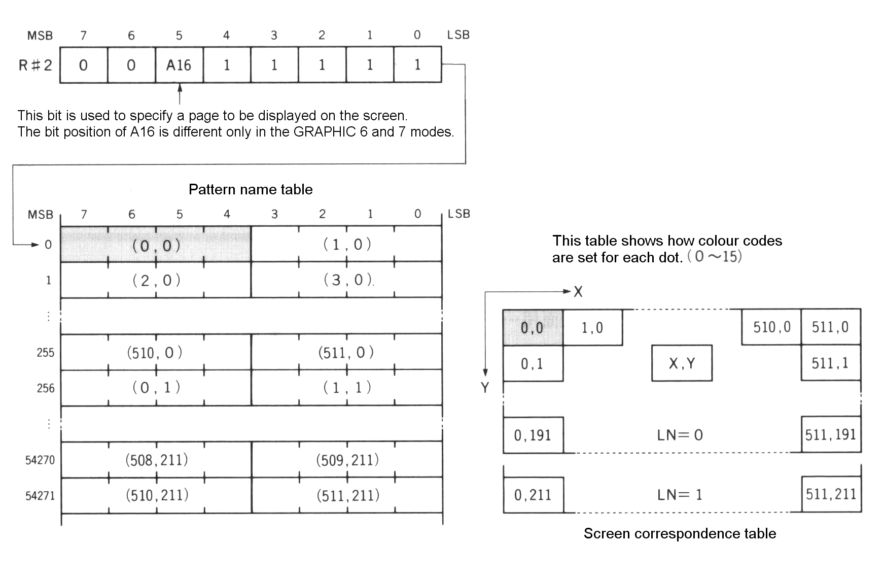
In GRAPHIC 6 mode, one byte of the pattern name table corresponds with 2 dots on the screen. The colour information of each dot is represented by 4 bits and 16 colours can be specified (see Figure 4.43). The starting address of the pattern name table is set by writing the high order bit of the address in R#2. The two addresses at which the pattern name table can be set ae either 00000H or 10000H. The dot at (X,Y) coordinate on the screen can be accessed by using Expression 4.3. The program of List 4.4 illustrates this.
Figure 4.43 Pattern name table structure of GRAPHIC 6 mode
The dot at (X,Y) coordinate on the screen can be accessed by using Expression 4.1. The program of List 4.2 illustrates the use of Expression 4.1.
Expression 4.3 The expression for the access to the dot at (X,Y) coordinate
ADR = X/2 + Y * 256 + base address
(The colour of the dot is represented by 4 high order bits in the case that X is even and by 4 low order bits in the case that X is odd.)
List 4.4 PSET for GRAPHIC 6 mode written in BASIC
100 '*********************************************
110 '  LIST 4.4   dot access of GRAPHIC 6 mode
120 '*********************************************
130 '
140 SCREEN 7
150 BA=0
160 FOR I=0 TO 511
170   X=I: Y=I\2: COL=15: GOSUB 1000
180 NEXT
190 END
200 '
1000 '*************************************************
1010 '  PSET (X,Y)
1020 '   COL:color  BA:graphic Base Address
1030 '*************************************************
1040 '
1050 ADR=X\2+Y*256+BA
1060 IF X AND 1 THEN BIT=&HF: C=COL ELSE BIT=&HF0: C=COL*16
1070 VPOKE ADR,(VPEEK(ADR) AND BIT) OR COL
1080 RETURN
3.8.3 Setting screen colour
The border colour of the screen can be specified by R#7 (see Figure 4.44).
Figure 4.44 Screen colour specification in GRAPHIC 6 mode

3.9 GRAPHIC 7 Mode Use
GRAPHIC 7 mode is described as follows:
----------------------------------------------------------------------------
| screen:               256 (horizontal) x 212 (vertical) dots             |
|                       (or, 192 vertical)                                 |
|                       256 colours can be displayed at the same time      |
| command:              graphic command by hardware available              |
| sprite:               mode 2 sprite function available                   |
| memory requirements:  for 192 dots                                       |
|                         bitmap screen ....... 48K bytes (C000H bytes)    |
|                         (8 bits x 256 x 192)                             |
|                       for 212 dots                                       |
|                         bitmap screen ....... 53K bytes (D400H bytes)    |
|                         (8 bits x 256 x 212)                             |
|                       Note that this mode cannot be used with 64K byte   |
|                       VRAM machines, as in the case of GRAPHIC 6         |
| BASIC:                compatible to SCREEN 8                             |
----------------------------------------------------------------------------
3.9.1 Setting GRAPHIC 7 mode
Set GRAPHIC 7 mode as shown in Figure 4.45.
Figure 4.45 GRAPHIC 4 mode setting

3.9.2 Pattern name table
Configuration of GRAPHIC 7 mode is the simplest of all modes; one dot on the screen corresponds with one byte in the pattern name table. The value of one byte written in the table represents 256 kinds of colours. The starting address of the pattern name table is set by R#2. The two addresses at which the pattern name table can be set are either 00000H or 10000H (see Figure 4.46).
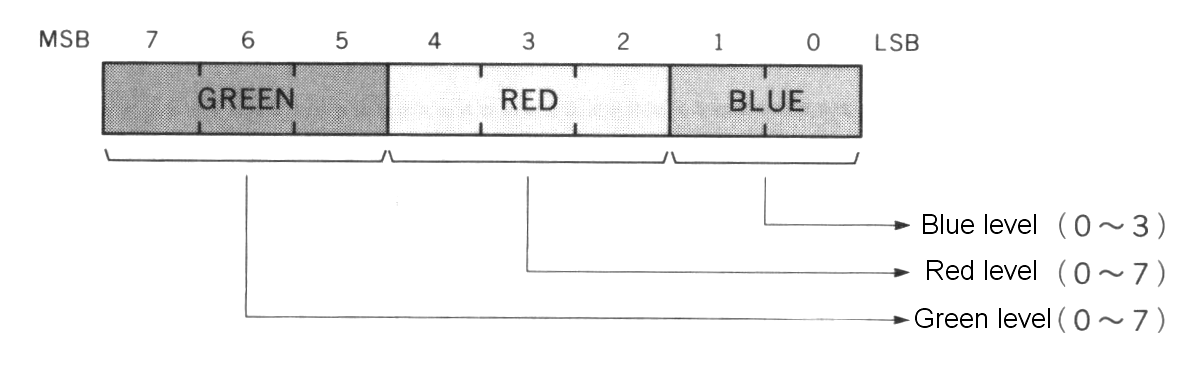
One byte of data represents the intensity of 3 bits for green, 3 bits for red, and 2 bits for blue, as shown in Figure 4.47. The dot at (X,Y) coordinate on the screen can be accessed by using Expression 4.4.
Figure 4.46 Pattern name table structure of GRAPHIC 7 mode
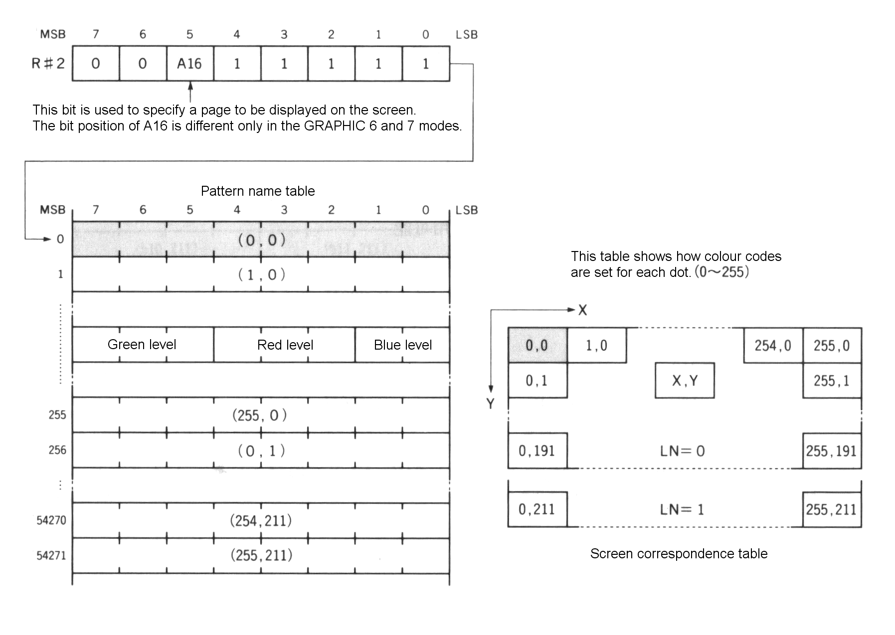
Figure 4.47 RGB brightness information
Expression 4.4 The expression for accessing to the dot at (X,Y) coordinate
ADR = X + Y * 256 + base address
3.9.3 Setting the screen colour
The border colour of the screen can be specified by R#7 (see Figure 4.48).
Figure 4.48 Screen colour specification in GRAPHIC 7 mode
4. MISCELLANEOUS FUNCTIONS FOR THE SCREEN DISPLAY
Detailed settings for the screen display are available in MSX-VIDEO. These include screen ON/OFF and specification of the display location. These MSX-VIDEO functions are described in this function.
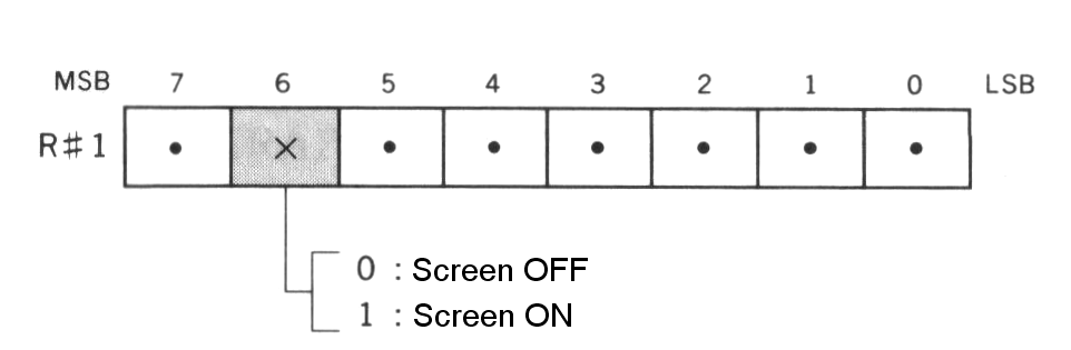
Screen ON/OFF
The screen ON/OFF function is controlled by bit 6 of R#1 (see Figure 4.49). When set OFF, the entire screen changes to the colour specified by the 4 low order bits of R#7 (8 bits in GRAPHIC 7 mode). Drawing with the VDP commands is faster when the screen is set OFF.
Figure 4.49 Screen ON/OFF
BASIC program lines:
   VDP(1)=VDP(1) AND &B10111111 ⟵ Screen OFF
   VDP(1)=VDP(1) OR  &B01000000 ⟵ Screen ON
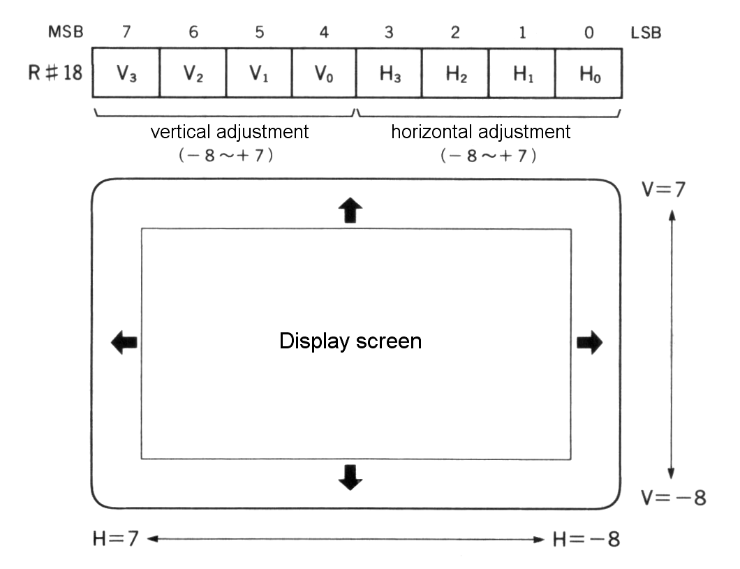
Adjustment of the display location on the screen
R#18 is used for adjusting the display location on the screen (see Figure 4.50). This corresponds with the “SET ADJUST” instruction of BASIC.
Figure 4.50 Adjustment of the screen display
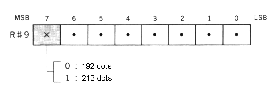
Switching the number of pixels in the Y direction
The number of dots displayed in the Y direction on the screen can be switched to either 192 dots or 212 dots by setting bit 7 of R#9 to 0 or 1. This function is only valid for five screen modes, TEXT 2, and GRAPHIC 4 to GRAPHIC 7 modes. When 212 dots are set in TEXT 2 mode, the number of text lines is 26.5 (=212/8) and on the 27th line only the upper halves of characters are displayed.
Figure 4.51 Switching the number of dots in the vertical direction
BASIC program lines:
   VDP(10)=VDP(10) AND &B01111111 ⟵ 192 dots
   VDP(10)=VDP(10) OR  &B10000000 ⟵ 212 dots
Switching the display page
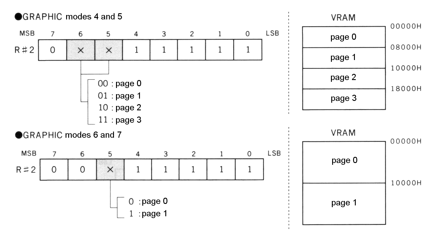
In GRAPHIC modes 4 to 7, the display pages can be easily switched by setting the starting address of the pattern name table using R#2. In fact, the second parameter of the “SET PAGE” BASIC instruction switches the display page this way.
Figure 4.52 Switching pages
Automatic alternate screen display
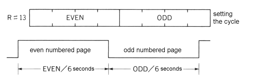
In GRAPHIC modes 4 to 7, two pages can be displayed alternately by using the following method. Either page 0 and page 1, or page 2 and page 3 can be displayed alternately.
To begin the alternate display, select the odd-numbered page (1 or 3) using R#2 and set the screen alternation rate in R#13. The 4 high order bits of R#13 represent the time for displaying the even page and the 4 low order bits represent the time for displaying the odd page. The time is set in 1/6 seconds interval. Setting 0 for both time periods causes only the odd page to be displayed.
Figure 4.53 Setting the rate of the screen alternation
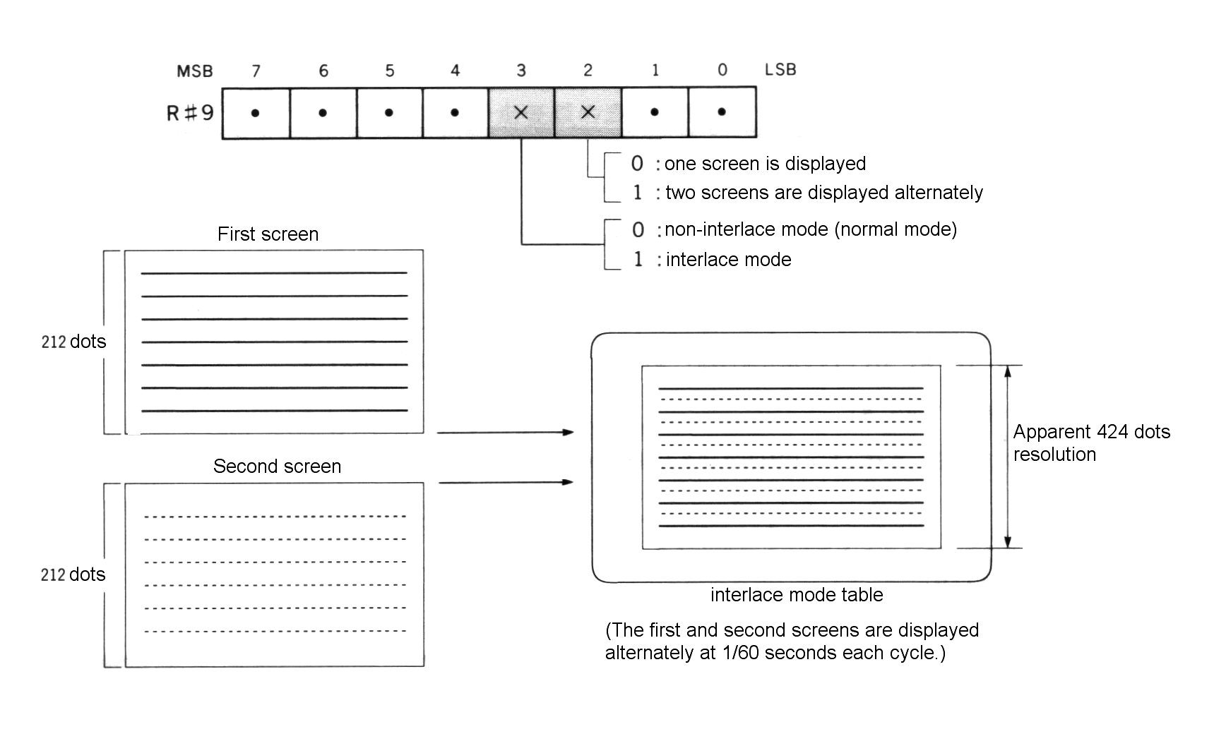
Setting the interlaced mode
The interlaced mode allows an apparent screen resolution in the Y direction of double the normal mode. A resolution of up to 424 dots in the Y direction can be achieved using this mode. This is done by alternating at high speed the normal screen and a screen whose scanning lines are offset vertically by half a line. In MSX-VIDEO the interlaced mode is specified by setting bit 3 of R#9 ro “1”. The two screens are switched 60 times a second.
When the odd page is selected in GRAPHIC 4 to GRAPHIC 7 screen modes and the alternate screen display mode is selected, the screen is normally switched at slow rates specified in units of 1/6 seconds. However, combinig this function and the interlaced function can make the number of the vertical dots of the display screen seem double.
Figure 4.54 Setting the interlaced mode
List 4.5 Interlaced mode example
1000 '***************************************************
1010 '  [List 4.5](#list-45--interlaced-mode-example)  interlace mode
1020 '***************************************************
1030 '
1040 COLOR 15,0,0 : SCREEN 5,,,,,0     'noninterlace mode
1050 '
1060 SET PAGE 0,0 : CLS
1070 LINE (32,0)-(64,120),15,BF
1080 SET PAGE 1,1 : CLS
1090 LINE (192,91)-(224,211),15,BF
1100 '
1110 VDP(10)=VDP(10) OR &B00001100     'interlace mode!!!
1120 '
1130 FOR I=32 TO 192
1140   SET PAGE 1,0
1150   LINE (I,0)-STEP(0,120),0
1160   LINE (I+33,0)-STEP(0,120),15
1170   SET PAGE 1,1
1180   LINE (256-I,91)-STEP(0,120),0
1190   LINE (221-I,91)-STEP(0,120),15
1200 NEXT I
1210 '
1220 VDP(10)=VDP(10) AND &B11110011    'interlace off
Vertical scroll of the screen
R#23 is used to set the line at which display begins on the screen. Changing this register enables vertical scrolling of the screen. Note that, since the scroll is done every 256 lines, the sprite tables should be moved to another page. List 4.6 shows an example.
List 4.6 Vertical scroll example
1000 '**************************************************************
1010 '  List 4.6  Hardware scroll
1020 '**************************************************************
1030 '
1040 SCREEN 5,2: COLOR 15,0,0: CLS
1050 COPY (0,0)-(255,43) TO (0,212),,PSET   'erase (212,0)-(255,255)
1060 '
1070 FOR I=1 TO 8: D(I)=VAL(MID$("00022220",I,1))-1: NEXT
1080 '
1090 OPEN "GRP:" AS #1
1100 FOR I=0 TO 3
1110   PRESET (64,I*64): PRINT #1,"Hit CURSOR Key"
1120 NEXT
1130 '
1140 J=STICK(0)
1150   P=(P+D(J)) AND &HFF
1160   VDP(24)=P
1170 GOTO 1140
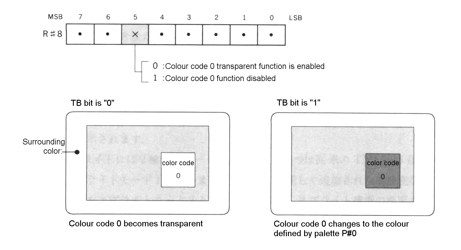
Specifying the colour code 0 function
Among the 16 colour codes, only code 0 can be made as a “transparent” colour (the border colour of the screen can be set transparently), the colour set in palette P#0. Setting bit 5 of R#8 to “1” disables thsi function and the colour code 0 changes to the colour defined by the palette P#0.
Figure 4.55 Colour code 0 function
Generating interrupts by the scanning line location
In MSX-VIDEO an interrupt can be generated just after the CRT finishes displaying a specific scanning line. Set in R#19 the number of the scanning line at which the interrupt should be generated, and set bit 4 of R#0 to “1” (see Figure 4.56).
Figure 4.56 Generating the scanning line interrupt

5. SPRITES
Sprites are used to display movable character patterns of 8 x 8 or 16 x 16 dots on the screen. This function is especially useful in the programming of games.
The parameters specified are the X and Y coordinates, the character number, and the colour code. The sprite is displayed by writing this data to the preset sprite attribute table.
There are two modes for MSX2 sprites. Mode 1 is compatible to the TMS9918 used in the MSX1 machines. Mode 2 includes several improved functions and has been implemented on the MSX2. This section summarises the sprite function and describes the two modes.
5.1 Sprite Function
Up to 32 sprites can be displayed on one screen at a time.
Sprites have two sizes, 8 x 8 and 16 x 16 dots. Only one size can be displayed on the screen at a time. The size of one dot of the sprite is usually the same as one pixel, but in the case of GRPAHIC5 and 6 modes (for both, the resolution is 512 x 212) the horizontal size is two pixels, that is, the absolute size of the sprite is the same in any mode.
The Sprite mode automatically selected is determined by the screen mode in use. Shown below are the default settings:
Sprite mode 1 selected: ....... GRAPHIC 1       (SCREEN 1)
                                GRAPHIC 2       (SCREEN 2)
                                MULTI colour    (SCREEN 3)

Sprite mode 2 selected: ....... GRAPHIC 3       (SCREEN 4)
                                GRAPHIC 4       (SCREEN 5)
                                GRAPHIC 5       (SCREEN 6)
                                GRAPHIC 6       (SCREEN 7)
                                GRAPHIC 7       (SCREEN 8)
5.2 Sprite mode 1
Sprite mode 1 has the same functions as the sprite mode of MSX1 machines. Thus programs using this mode can also be run on the MSX1.
5.2.1 Number of sprites to be displayed
There are 32 sprites numbered from 0 to 31. Sprites with the smallest numbers have the highest priority. When sprites are placed on the same horizontal line of the screen, up to 4 sprites are placed in their order priority, and the portions of the 5th sprite or higher which conflict with the existing four sprites on a given line are not displayed.
Figure 4.57 Number of sprites to be displayed (sprite mode 1)
-------------------------------------------------------------------------
|                                                                       |
|            --------     --------            --------                  |
|  --------  |  #2  |     |  #3  |  --------  |  #5  |                  |
|  |  #1  |  |      |     |      |  |  #4  |  :      :   ::::::::       |
|  |      |  --------     --------  |      |  ::::::::   :  #6  :       |
|  --------                         --------             |      |       |
|                                                        --------       |
|                                                                       |
|                                                                       |
|                                                                       |
-------------------------------------------------------------------------
5.2.2 Sprite display settings
The following descriptions are settings to display the sprite.
Setting the size of the sprite
8 x 8 dots or 16 x 16 dots can be set (see Figure 4.58). By default, 8 x 8 dots is selected.
Figure 4.58 Setting the size of the sprite
    MSB   7    6    5    4    3    2    1    0    LSB
        -----------------------------------------
R#1     | .  | .  | .  | .  | .  | .  | X  | .  |
        -----------------------------------------
                                        |    0: 8 x 8 dots
                                        +-->
                                             1: 16 x 16 dots

  8 x 8 dots                             16 x 16 dots
-------------- -                ------------------------------  -
|            | ^                |                            |  ^
|            | |                |                            |  |
|            | 8 dots           |                            |  |
|            | |                |                            |  |
|            | V                |                            |  |
-------------- -                |                            | 16 dots
|<- 8 dots ->|                  |                            |  |
                                |                            |  |
                                |                            |  |
                                |                            |  |
                                |                            |  V
                                ------------------------------  -
                                |<---    16 x 16 dots    --->|
Expanding the sprite
Figure 4.59 shows how to select whether one dot of the sprite corresponds to one dot of the screen or whether it is expanded double in both the horizontal and vertical directions. By default, the one dot to one dot size is selected.
Figure 4.59 Expanding the sprite
    MSB   7    6    5    4    3    2    1    0    LSB
        -----------------------------------------
R#1     | .  | .  | .  | .  | .  | .  | .  | X  |
        -----------------------------------------
                                             |    0: normal mode
                                             +-->
                                                  1: expansion mode (2X)
Setting the sprite pattern generator table
Sprite patterns are defined in the sprite pattern generator table in VRAM. Up to 256 sprites can be defined in the case of 8 x 8 dots, and up to 64 for 16 x 16 dots. Each pattern is numbered from 0 to 255 and is allocated in VRAM as shown in Figure 4.60. For 16 x 16 dots, four 8 x 8 patterns are used from the top of the table. In this case, using any number of these four patterns causes the same sprite to be specified. R#6 is used to set the address in the sprite pattern generator table as shown in Figure 4.60.
Figure 4.60 Structure of the sprite pattern generator table (sprite mode 1)
            VRAM

      |<-- 1 byte  -->|
  -   ----------------- ---+  <--- R#6
  ^   |               |    |       -----------------------------------------
  |   |               |    |       |  0 |  0 | A16| A15| A14| A13| A12| A11|
  |   |               |    |       -----------------------------------------
  8   |               | Pattern
bytes |               |   #0
  |   |               |    |
  |   |               |    |
  V   |               |    |
  -   |---------------| ---+
      |               |    |
      |               |    |
      |               |    |
      |               | Pattern
      |               |   #1
      |               |    |
      |               |    |
      |               |    |
      |---------------| ---+
      |       .       |
              .
              .
      |               |
      |---------------| Pattern #255
      |               |
Setting the sprite attribute table
Each sprite is displayed in one of 32 “sprite planes” exclusively, and the sprite status for each sprite plane is recorded using 4 bytes. The area having the information for each sprite plane is called the sprite attribute table. The starting address in VRAM for this table is set in R#5 and R#11 as shown in Figure 4.61.
The four bytes in the attribute table contain the following information:
- Y-coordinate: specifies Y-coordinate of the sprite. Note that the top line of the screen is not 0 but 255. Setting this value in 208 (D0H) causes sprites after this plane not to be displayed.
- X-coordinate: specifies X-coordinate of the sprite.
- pattern number: specifies the character in the sprite pattern generator table to be displayed.
- colour code: specifies the colour (palette number) of the portion where the bit of the sprite pattern is “1”. * EC: Setting “1” to this bit causes the sprite to be shifted for 32 bits to the left. Using this function enables the dot of the sprite to be displayed one by one from the left edge of the screen.
Figure 4.61 Structure of the sprite attribute table (sprite mode 1)
    MSB   7    6    5    4    3    2    1    0    LSB
    -   ----------------------------------------- --+  ⟵ (*)
    ^   |    :   Y coordinate (0 to 255)   :    |   |
    |   |----+----+----+----+----+----+----+----|   |
    |   |    :   X coordinate (0 to 255)   :    |   |
4 bytes |----+----+----+----+----+----+----+----| Sprite #0 attribute area
    |   |    :  Pattern number (0 to 255)  :    |   |
    |   |----+----+----+----+----+----+----+----|   |
    V   | EC | 0  | 0  | 0  |    Colour code    |   |
    -   |----+----+----+----+----+----+----+----| --+
        |                                       |   |
        |                                       |   | Sprite #1 attribute area
                            .                       .
                            .                       .
                            .                       .

        |                                       |   | Sprite #31 attribute area
        |                                       |   |
        ----------------------------------------- --+

             -----------------------------------------
(*)  R#5     | A14| A13| A12| A11| A10| 1  | 1  | 1  |
             -----------------------------------------
             -----------------------------------------
     R#11    | 0  | 0  | 0  | 0  | 0  | 0  | A16| A15|
             -----------------------------------------


    -------------------------------------------
    |                                         |
    |    ---------------------------------    |
    |    |                               |    |
    |    |               |            ###|:   |
    |    |               |               |    |
    |    |               |             ##|::  |
    |    |               |               |    |     EC bit = "0"
    |    |               V              #|::: |
    |    |                               |    |
    |    |####                           |    |
    |    |  ^                            |    |
    |    ---+-----------------------------    |
    |       |                                 |
    --------+----------------------------------
            |
The sprite will display from here (X coordinate = 0)


    -------------------------------------------
    |                                         |
    |    ---------------------------------    |
    |    |                               |    |
    | :::|#              |               |    |
    |    |               |               |    |
    |  ::|##             |               |    |
    |    |               |               |    |     EC bit = "1"
    |   :|###            V               |    |
    |    |                               |    |
    |    |####                       ####|    |
    |    |                            ^  |    |
    |    -----------------------------+---    |
    |                                 |       |
    ----------------------------------+--------
                                      |
The sprite will display until here (X coordinate = 255)
5.2.3 Judging the sprite conflicts
When two sprites conflict, bit 5 of S#0 becomes “1” to inform of the conflict. A “conflict” means that bits “1” in the sprite pattern whose colour is not “transparent” occupy the same coordinate (see Figure 4.62)
Figure 4.62 Conflict of sprites (sprite mode 1)
    MSB   7    6    5    4    3    2    1    0    LSB
        -----------------------------------------
S#0     | .  | .  | X  | .  | .  | .  | .  | .  |
        -----------------------------------------
                    |    0: Normal
                    +-->
                         1: A sprite conflict exists


    +-- ---------------------                     ---------------------
    |   | \\\\\\\ |         |                     | \\\\\\\ |         |
    |   | \\\\\\\ |         | <--- Sprite 1 --->  | \\ -----+---------+-----
8 or 16 | \\\\\\\ |         |                     | \\ | xx | // |    |    |
 dots   |---------+---------+----------           |----+----- // |    |    |
    |   |         | /////// |         |           |    | /////// |    |    |
    |   |         | /////// |         |           |    |----------    |    |
    |   |         | /////// |         |           |    |              |    |
    +-- ----------+----------         |           -----+---------------    |
                  |                   | <- Sprite 2 -> |                   |
                  |                   |                ---------------------
                  |                   |
                  ---------------------

        These two sprites do not conflict         These two sprites conflict

------  ------
| \\ |  | // | --> This pattern bit has one part
------  ------
When more than 5 sprites are placed on the same line, bit 6 of S#0 becomes “1” and the identifying number of the 5th sprite (the portion which cannot be displayed) is set in the 5 low order bits of S#0.
Figure 4.63 Judging the conflict (sprite mode 1)
    MSB   7    6    5    4    3    2    1    0    LSB
        -----------------------------------------
S#0     | .  | X  | .  | X  | X  | X  | X  | X  |
        -----------------------------------------
               |       |                        |
               |       +------------------------+
               |   Identification number of fifth sprite on a single line
               |
               |    0: Normal
               +-->
                    1: More than 4 sprites are occupying a single line
5.3 Sprite Mode 2
Sprite mode 2 is the newly added mode for MSX-VIDEO. It is not compatible with TMS9918 and cannot be used with MSX1 machines.
5.3.1 Number of sprites to be displayed
The number of sprites which can be displayed on one screen is also 32, but up to eight sprites can be displayed on a given horizontal line of the screen. The priorities are the same as in mode 1 with the lower numbers having highest priority.
Figure 4.64 Number of sprites to be displayed (sprite mode 2)
----------------------------------------------------------------------------
|                                                                          |
|                                                                          |
|  -------           -------------  -------              -------           |
|  |  #0 |  -------  |  #2 |  #4 |  |  #5 |              |  #8 |           |
|  |     |  |  #1 |  |     |---  |  |     |---  -------  :     :  :::::::  |
|  -------  |     |  -------  |---  -------  |  |  #7 |  :::::::  :  #9 :  |
|           -------     |  #3 |        |  #6 |  |     |           |     |  |
|                       -------        -------  -------           -------  |
|                                                                          |
|                                                                          |
----------------------------------------------------------------------------
5.3.2 Sprite display settings
Sprite size
Same as sprite mode 1
Expanding sprite
Same as sprite mode 1
Sprite display ON/OFF
In sprite mode 2, the sprite display can be turned ON/OFF by bit 1 of R#8. When this bit is set to 1, no sprites will appear on the screen.
Figure 4.65 Sprite display specification
    MSB   7    6    5    4    3    2    1    0    LSB
        -----------------------------------------
R#8     | .  | .  | .  | .  | .  | .  | X  | .  |
        -----------------------------------------
                                        |    0: Sprite mode on
                                        +-->
                                             1: Sprite mode off
Setting the pattern generator table
Same as sprite mode 1
Sprite attribute table
In sprite mode 2, since different colours can be set for each horizontal line of the sprite, the colour information is stored in a sprite colour table as described below, which is independent of the sprite attribute table. Three kinds of information are stored in the sprite attribute table (see Figure 4.66).
- Y-coordinate: setting this value to 216 (D8H) causes sprites after this sprite plane not to be displayed. Except for this, it is the same as the sprite mode 1.
- X-coordinate: same as sprite mode 1.
- pattern number: same as sprite mode 1.
Figure 4.66 Structure of the sprite attribute table (sprite mode 2)
    MSB   7    6    5    4    3    2    1    0    LSB
    -   ----------------------------------------- --+  ⟵ (*)
    ^   |    :   Y coordinate (0 to 255)   :    |   |
    |   |----+----+----+----+----+----+----+----|   |
    |   |    :   X coordinate (0 to 255)   :    |   |
4 bytes |----+----+----+----+----+----+----+----| Sprite #0 attribute area
    |   |    :  Pattern number (0 to 255)  :    |   |
    |   |----+----+----+----+----+----+----+----|   |
    V   |    :    :    :  unused :    :    :    |   |
    -   |----+----+----+----+----+----+----+----| --+
        |                                       |   |
        |                                       |   | Sprite #1 attribute area
                            .                       .
                            .                       .
                            .                       .

        |                                       |   | Sprite #31 attribute area
        |                                       |   |
        ----------------------------------------- --+

             -----------------------------------------
(*)  R#5     | A14| A13| A12| A11| A10| 1  | 1  | 1  |
             -----------------------------------------
             -----------------------------------------
     R#11    | 0  | 0  | 0  | 0  | 0  | 0  | A16| A15|
             -----------------------------------------
Sprite colour table
The colour table is automatically set at the address 512 bytes before the starting address of the sprite attribute table. 16 bytes are allocated for each sprite plane and the following settings are made for each line of the sprite.
- colour code: colour can be specified for each line.
- EC: the same as EC bit of the attribute table of sprite mode one. When “1”, the sprite display location is shifted 32 bits to the left. This also can be specified for each line.
- CC: when CC bit is “1”, it can have the same priority as the sprite “that has the higher priority than this sprite and whose CC bit is “0” and that is nearest to this sprite plane”. When sprites having the same priority are overlapped, the colour for which OR (logical or) of both colour codes are displayed. In this case, the overlapping does not cause a conflict (see Figure 4.68).
- IC: (one line of) the sprite with this bit “1” does not conflict with other sprites.
Figure 4.67 Structure of the sprite colour table (sprite mode 2)
  MSB   7    6    5    4    3    2    1    0    LSB
      -----------------------------------------            --+ ⟵ starting address of the
   0  | EC | CC | IC | 0  |    Color  code    |  1st line    |    sprite colour table
      |----+----+----+----+----+----+----+----|              |
   1  | EC | CC | IC | 0  |    Color  code    |  2nd line    |
      |----+----+----+----+----+----+----+----|              |
      |                   .                   |              |
                          .                                  |
                          .                                  | Sprite #0 colour table
      |                                       |              |
      |----+----+----+----+----+----+----+----|              |
  15  | EC | CC | IC | 0  |    Color  code    |  16th line   |
      |----+----+----+----+----+----+----+----|            --+
      |                   .                   |            .
                          .                                .
                          .                                .
      |                                       |
      |----+----+----+----+----+----+----+----|            --+
 496  | EC | CC | IC | 0  |    Color  code    |  1th line    |
      |----+----+----+----+----+----+----+----|              |
 497  | EC | CC | IC | 0  |    Color  code    |  2nd line    | Sprite #31 colour table
      |----+----+----+----+----+----+----+----|              |
      |                   .                   |              |
                          .                                  |
                          .                                  |
      |                                       |              |
      |----+----+----+----+----+----+----+----|              |
 511  | EC | CC | IC | 0  |    Color  code    |  16th line   |    starting address of the
      -----------------------------------------            --+ ⟵ sprite attribute table
        |    |    |       |                   |
        |    |    |       +-------------------+
        |    |    |        Specify the colour code (0 to 15)
        |    |    |        for the sprite by each line
        |    |    |                                      1 = no
        |    |    +-------------------> detect conflict: 0 = yed
        |    |
        |    +------------------------> priority: 0 = yes
        |                                         1 = no
        |
        +-----------------------------> 32 dot left shifted display: 1 = yes
                                                                     0 = no
Figure 4.68 CC bit detection
     Sprite 1                    Sprite 2             Sprite 1,2 (overlapped)
-------------------         -------------------         -------------------
| ////////// |    |         | \\ |            |         | xx | ///// |    |
| ////////// |    |         | \\ |            |         | xx | ///// |    |
| ////////// |    |         | \\ -------------|         | xx --------+----|
| ////////// |    |         | \\\\\\\\\\\\\\\ |      +--| xxxxxxxxxx | \\ |
| ////////// |    |         | \\\\\\\\\\\\\\\ |      |  | xxxxxxxxxx | \\ |
-------------------         -------------------      V  -------------------
      CC = 0                      CC = 1             Color code = 8 or 4 = 12

------                      ------                      ------
| // | Color code = 8       | \\ | Color code = 4       | xx | Color code=12
------                      ------                      ------
Note:
- Conflicts are not detected when the pattern of the sprite whose CC is “1” is piled on the portion CC=0 of the sprite which has a smaller number and is nearest to it.
- To display the sprite whose CC is “1”, CC bit of the sprite which has smaller number should be set to 0.
5.3.3 Judging sprite conflicts
A “conflict” in sprite mode 2 occurs when the display colour of a sprite is not transparent and “1” bits on the line whose CC bit is 0 overlap each other. When two sprites conflict, bit 5 of S#0 becomes “1” and the conflict can be detected (see Figure 4.69). In this case, different from the sprite mode 1, the coordinate where the conflict occurred can be detected by S#3 to S#6 as shown in Figure 4.70. Note that the coordinate which can be obtained by these registers is not the coordinate where the conflict actually occurred. To get this, use Expression 4.5. S#3 to S#6 are reset when S#5 is read out.
Figure 4.69 Conflict of the sprite (sprite mode 2)
    MSB   7    6    5    4    3    2    1    0    LSB
        -----------------------------------------
S#0     | .  | .  | X  | .  | .  | .  | .  | .  |
        -----------------------------------------
                    |    0: normal
                    +-->
                         1: conflict occurred


        ----------------------------
        |                          |
        |  --------------------    |
        |  | \\\\\\\\\\\\\\\\ |    |
        |  | \\\\\\\\\\\\\\\\ |    |
        |  | \\\\\\\ ---------+----+-----------
        |  | \\\\\\\ | \\\\\\ |    |          |
        |  | \\\\\\\ | \\\\\\ |    |          |
        |  | \\\\\\\ | \\\\\\ |    |          |
        |  | \\\\\\\ | \\\\\\ |    |          |   the attribute of this line
        -  | \\\\\\\ | \ -----+----+--------  -     -------------------------
    +-- |  | \\\\\\\ | \ | xx | // | ///// |  | --> |  | 0| 0|  :  :  :  :  |
    |   -  ----------+---+----- // | ///// |  -     -------------------------
    |   |            |   | /////// | ///// |  |        |     |
    |   -------------+---+---------- ///// |  |        +-----+
    |                |   | /////////////// |  |   CC and IC bits are both "0"
    | the attribute  |   -------------------  |
    | of this line   |                        |
    |                |                        |
    |                --------------------------
    V
-------------------------
|  | 0| 0|  :  :  :  :  |
-------------------------
   |     |
   +-----+
CC and IC bits are both "0"
Figure 4.70 Readout of the conflict coordinate
    MSB   7    6    5    4    3    2    1    0    LSB
        ----------------------------------------- --+
S#3     | X7 | X6 | X5 | X4 | X3 | X2 | X1 | X0 |   |
        -----------------------------------------   |
                                                    | X-coordinate where the conflict occurred
        -----------------------------------------   |
S#4     | 1  | 1  | 1  | 1  | 1  | 1  | 1  | X8 |   |
        ----------------------------------------- --+

        ----------------------------------------- --+
S#5     | Y7 | Y6 | Y5 | Y4 | Y3 | Y2 | Y1 | Y0 |   |
        -----------------------------------------   |
                                                    | Y-coordinate where the conflict occurred
        -----------------------------------------   |
S#6     | 1  | 1  | 1  | 1  | 1  | 1  | Y9 | Y8 |   |
        ----------------------------------------- --+
Expression 4.5 Calculating the actual conflict coordinate
    (X-coordinate where the conflict occurred) = (X-coordinate of S#3 and S#4) - 12
    (Y-coordinate where the conflict occurred) = (Y-coordinate of S#5 and S#6) - 8
When more than nine sprites are placed on the same horizontal line, bit 6 of S#0 becomes “1” and the number of the sprite plane whose order of priority is 9 is entered to the 5 low order bits of S#0 (see Figure 4.71).
Figure 4.71 Conflict of the sprite (sprite mode 2)
    MSB   7    6    5    4    3    2    1    0    LSB
        -----------------------------------------
S#0     | .  | X  | .  | X  | X  | X  | X  | X  |
        -----------------------------------------
               |       |                        |
               |       +------------------------+
               |     contains the 9th sprite number
               |
               |    0: normal
               +-->
                    1: more than 9 sprites are occupying the same line
Changes from the original:
-
In Figure 4.3, “Port#17” indication is corrected to “R#17”.
-
In Figure 4.4, “00” field in R#17 is corrected to “10”.
-
In section 3.2.2, subsection “Pattern name table”, text “12 low order bits o the address (A9 to A0)” is corrected to “12 low order bits of the address (A11 to A0)”
-
In Figure 4.17, the numerations of the two last rows in the Screen correspondence table, originally “22” and “23”, are corrected to “25” and “26” respectively.
-
In section 3.2.2, subsection “Blink table”, the text “the 9 low order bits of the address (A9 to A0)” is corrected to “the 8 low order bits of the address (A8 to A0)”.
-
In Figure 4.25, indication “Specifies the value of the screen (0 to 15)” is changed to “Specifies the border colour (0-15)”.
-
In Figure 4.34, in the screen correspondance table, the three stages of the screen are named “Upper stage of screen” in the original. This is corrected, and the stages are named “Upper”, “Middle” and “Lower”.
-
The title of section 3.6.3 is “Screen colour mode specification” in the original. The word “mode” is erased.
-
In section 3.8.2, the text “by writing the 2 high order bits” is corrected to “by writing the high order bit”.
-
The title of Figure 4.63 is “Judging the conflict (sprite mode 2)” in the original. This is corrected to “Judging the conflict (sprite mode 1)”.
-
In Figure 4.68, indication “Color code = 8 or 4 or 12” is changed to “Color code = 8 or 4 = 12”.